Conjugate cam driving mechanism with error compensation function

A technology of conjugate cam and drive mechanism, which is applied in the directions of sending objects, thin material handling, transportation and packaging, etc., can solve the problem of not being able to ensure the close fit of the auxiliary cam and the roller, so as to prevent vibration and noise, and prolong the service life. Effect

Active Publication Date: 2013-01-30
SHANGHAI YOCO PRINTING MACHINERY
View PDF6 Cites 8 Cited by
  • Summary
  • Abstract
  • Description
  • Claims
  • Application Information

AI Technical Summary

Problems solved by technology

However, none of the above methods can adapt to the systematic error generated by the cam mechanism as a whole, because the systematic error causes the gap between the secondary cam and the roller contact surface to change continuously during the rotation of the cam, and the fixed adjustment method cannot ensure The secondary cam fits closely with the roller

Method used


Image

  • Conjugate cam driving mechanism with error compensation function
  • Conjugate cam driving mechanism with error compensation function

Examples


Embodiment Construction

[0010] In order to better understand the technical solution of the present invention, it will be described in detail below through specific embodiments in conjunction with the accompanying drawings:

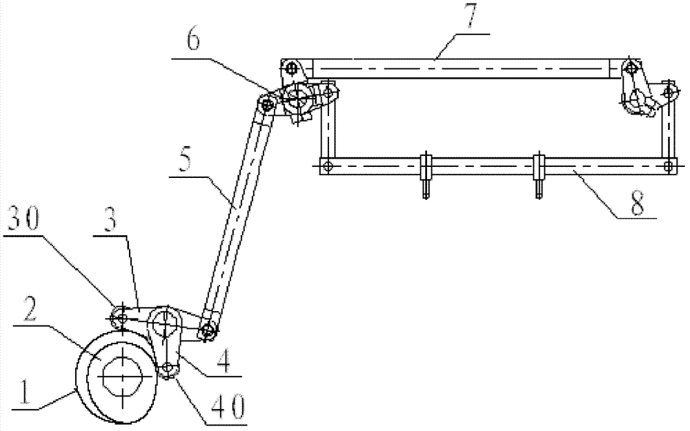
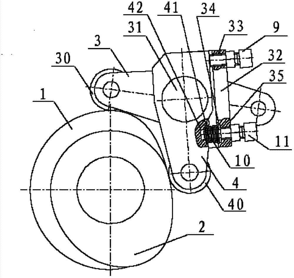
[0011] see figure 2 combined reference figure 1 , the conjugate cam driving mechanism with error compensation of the present invention includes a main cam 1, a secondary cam 2, a first lower swing link 3, a second lower swing link 4, a lower link 5, a pair of upper swing links 6. A pair of upper connecting rods 7, finished frame 8, an angle adjustment screw 9, a butterfly spring 10, and a pressure adjustment screw 11, among which:

[0012] The auxiliary cam 2 is installed on the transmission shaft of the main cam 1, and the outer peripheral curve of the auxiliary cam 2 is different from that of the main cam 1, so that the main cam 1 and the auxiliary cam 2 form a group of conjugate cam pairs;

[0013] The rotation center hole of the first down swing link 3 is sleeved on a swin...


PUM


Abstract

The invention discloses a conjugated cam driving mechanism with an error compensation function. The conjugated cam driving mechanism comprises a main cam, an auxiliary cam, a first lower oscillating bar, a second lower oscillating bar, an angle modulating screw and a belleville spring. The second lower oscillating bar is arranged on the front surface of the first lower oscillating bar, the upper end of the second lower oscillating bar is fixed onto an oscillating axle of the first lower oscillating bar, the second lower oscillating bar and the first lower oscillating bar form a T-shaped oscillating bar, a guiding blind hole is arranged on a side surface of the second lower oscillating bar back to the auxiliary cam, a compensation block is perpendicularly connected onto the front surface of the first lower oscillating bar, a limiting blind hole which is opposite to the guiding blind hole and is coaxial with the guiding blind hole is arranged on the lower portion of the compensation block, and a threaded through hole parallel to the limiting blind hole is arranged on the upper portion of the compensation block; the angle modulating screw is screwed in the threaded through hole of the first lower oscillating bar, and an end of the angle modulating screw is abutted to the side surface of the second lower oscillating bar back to the auxiliary cam; and the belleville spring is arranged between the guiding blind hole of the second lower oscillating bar and the limiting blind hole of the first oscillating bar.

Description

technical field [0001] The invention relates to a mechanism on an automatic die-cutting machine, in particular to a conjugate cam drive mechanism with error compensation for the reciprocating movement of the upper frame of the waste cleaning and cleaning products on the flat-press flat-horizontal automatic die-cutting machine. Background technique [0002] In the prior art, clearing finished products is a die-cutting processing method of post-press products applied in automatic die-cutting machines. The automatic die-cutting machine with the function of cleaning finished products is composed of a paper feeding unit, a die-cutting unit, a waste stripping unit, a finished product cleaning unit and a waste side discharge unit. After being processed by the die-cutting and waste-removing unit of the automatic die-cutting machine, the printed products are collected and stacked by the finished product-clearing mechanism. The driving mechanism of the cleaning waste product and the ...

Claims


Application Information

Patent Timeline
IPC IPC(8): B65H35/10
Inventor 蔡梁
Owner SHANGHAI YOCO PRINTING MACHINERY
Why Eureka
Try Eureka