Elevator rolling guide shoe with brake function

A technology for rolling guide shoes and elevators, applied in the directions of transportation, packaging, elevators, etc., can solve the problems of undiscovered emergency braking of elevator car, lack of guide wheel stop mechanism, mutual interference, etc.

Inactive Publication Date: 2013-01-30
SHANGHAI UNIV
View PDF9 Cites 35 Cited by
  • Summary
  • Abstract
  • Description
  • Claims
  • Application Information

AI Technical Summary

Problems solved by technology

[0013] However, the first two patents still retain the safety gear system. With the current increase in the popularity of elevators, the probability of safety gear not being regularly maintained is also greatly increased, and the problem of failure of the elevator braking mechanism still exists, so it cannot be fundamentally solved. To solve the problem of elevator safety, in addition, the wheels used to detect the speed of the elevator car and contact the guide rail have some functional overlap with the elevator rolling guide shoes, and the two will interfere with each other, resulting in the possibility of both functions Descent, which affects the vibration reduction and emergency braking of the elevator car, also brings maintenance problems
The third patent obviously does not have the function of emergency braking of the elevator car. To some extent, although the hydraulic cylinder can drive the supporting rocker arm of the guide wheel to rotate around the axis of rotation of the rocker arm, to provide a gap between the guide wheel and the guide rail. However, in addition to the friction surface of the guide wheel and the guide rail, there is also the friction surface of the guide wheel and the rotation axis of the guide wheel between the guide wheel and the guide rail. The compression force provided by the hydraulic cylinder is not enough to stop the guide wheel from rotating, that is, The device lacks a practicable stop mechanism for the guide wheel
[0014] After searching the Chinese patents, no inventions related to the emergency braking of the elevator car were found by the rolling guide shoes of the elevator

Method used


Image

  • Elevator rolling guide shoe with brake function
  • Elevator rolling guide shoe with brake function
  • Elevator rolling guide shoe with brake function

Examples


Embodiment 1

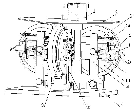
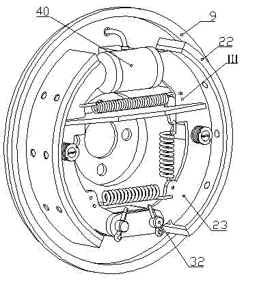
[0030] see Figure 1~Figure 3, the elevator rolling guide shoe with braking function, including: rolling guide wheel mechanism (I), hydraulic actuator (II) and stop mechanism (III), characterized in that: the rolling guide wheel mechanism (I) The three guide wheels (50) are closely attached to the three working surfaces of the T-shaped guide rail (1), the hydraulic actuator is connected with each guide wheel (50) of the rolling guide wheel mechanism, and the stop mechanism ( Ⅲ) Integrated inside the guide wheel (50); when the elevator stalls, whether it is ascending or descending, the stop mechanism (Ⅲ) can stop the guide wheel (50) from rotating, and cooperate with the pressing force provided by the hydraulic actuator , so that the guide wheel (50) hugs the guide rail (1) to realize emergency braking.

Embodiment 2

[0032] see Figure 1~Figure 8 , the present embodiment is basically the same as Embodiment 1, and the special features are as follows:

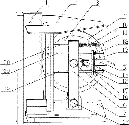
[0033] The elevator rolling guide shoe with braking function is characterized in that: the rolling guide wheel mechanism (I) includes a brake drum (3), a wear-resistant rubber layer (4), a guide shoe base (7), The main swing rod (6), the secondary swing rod (8), the limit spring (10), and the connecting long rod (20), wherein the outer layer of the brake drum (3) is inlaid with a wear-resistant rubber layer (4) to form Guide wheel (50), main and minor fork (6,8) lower ends are all hinged with guide shoe base (7), two fork ( A rotating shaft (16) is installed between 6 and 8), the brake drum (3) is installed on the rotating shaft (16), and the first connecting rod (20) passes through the main swing rod on the side of the guide wheel (50) (6) After connecting with the fixed vertical column of the guide shoe base (7), the limit spring (10) is ...

Embodiment 3

[0037] The specific structure of this embodiment is described in detail as follows:

[0038] figure 2 Shown is the three-dimensional structure diagram of the elevator guide shoe and the guide wheel, and the two side guide wheels have the same working structure. Refer to the following figure 2 , the general structure of the rolling guide wheel mechanism (I) in the present invention will be described.

[0039] The rolling guide wheel mechanism includes brake drum (3), wear-resistant rubber layer (4), guide shoe base (7), primary and secondary swing bars (6, 8), limit spring (10), connecting rod (20 ). Among them, the guide shoe base (7) is fixed to the elevator car, the brake drum (3) rotates around the guide wheel rotation axis (16), and can swing around the swing lever rotation axis (17) along with the main swing lever (6). The brake drum (3) is covered with wear-resistant rubber (4) and is in contact with the front of the T-shaped guide rail (1). The first connecting lo...


PUM


Abstract

The invention provides an elevator rolling guide shoe with a brake function. The elevator rolling guide shoe is provided with a rolling guide wheel mechanism, hydraulic execution mechanisms and stop mechanisms, wherein three guide wheels of the rolling guide wheel mechanism cling to three working surfaces of a T-shaped guide rail and are used for limiting the horizontal movement of an elevator car; the hydraulic execution mechanisms are connected with the guide wheels of the guide shoe and used for determining whether pressures are applied to the guide wheels according to a detected elevator running state; and the stop mechanisms are integrated in the guide wheels and used for stopping the guide wheels when an elevator is in a post stall state and enabling the guide wheels to tightly hold the guide rail in combination with pressing forces provided by the hydraulic execution mechanisms, so that the emergency braking is achieved; and each stop mechanism is composed of the following parts: a guide shoe base, a long connecting rod, a main swing rod, a secondary swing rod, a brake bottom plate, a hydraulic wheel cylinder, a brake shoe, a brake pad and a brake drum covered by wear-resistant rubber.

Description

technical field [0001] The invention relates to a rolling guide shoe for an elevator, in particular to an elevator rolling guide shoe with a braking function, which is stopped by the guide wheel of the elevator guide shoe and is connected to the T-shaped guide rail of the elevator under the action of the pressing force provided by the actuator. Hold to realize emergency braking of the elevator car when the elevator stalls. Background technique [0002] Generally speaking, the rolling guide shoe is between the elevator guide rail and the car, which can make the car move up and down along the guide rail, and replace the sliding friction with rolling friction, so as to reduce the vibration and noise during the operation of the elevator and improve the riding comfort. The comfortable passive vibration reduction device does not have the function of emergency braking of the elevator car. And present elevator is mainly to make elevator emergency brake on guide rail when overspeed,...

Claims


Application Information

Patent Timeline
Patent Type & Authority Applications(China)
IPC IPC(8): B66B7/04B66B5/18
Inventor 陈红冯永慧冯玉豹刘高
Owner SHANGHAI UNIV
Why Eureka
Try Eureka