Enamel heat-insulation tube

A thermal insulation pipe and enamel technology, which is applied in the direction of heat preservation and protection of pipes and pipes through heat insulation, can solve the problems of high cost, difficult production, and easy deformation of thermal insulation pipes, and achieves low price, good heat absorption, and easy deformation effect

Inactive Publication Date: 2013-01-30
YIKEBO ENERGY TECH SHANGHAI
View PDF1 Cites 2 Cited by
  • Summary
  • Abstract
  • Description
  • Claims
  • Application Information

AI Technical Summary

Problems solved by technology

[0003] The purpose of the present invention is to provide an enamel heat preservation pipe to solve the problems of high cost, difficult manufacture and easy deformation of the existing heat preservation pipe

Method used


Image

  • Enamel heat-insulation tube
  • Enamel heat-insulation tube

Examples


Embodiment Construction

[0011] The specific embodiments of the present invention will be described in detail below in conjunction with the accompanying drawings.

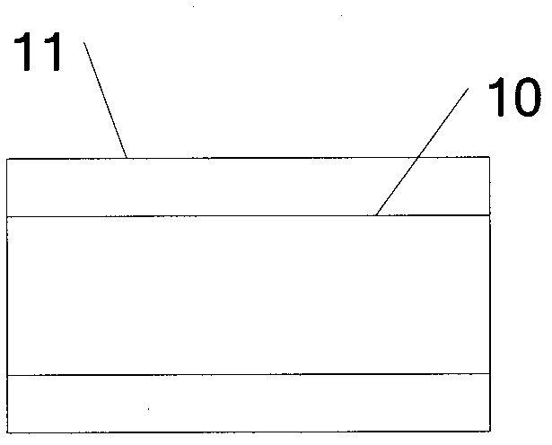
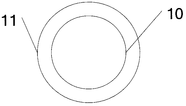
[0012] First, please refer to figure 1 , figure 1 It is a sectional view of the enamel insulation pipe of the present invention, from figure 1 It can be seen that the present invention proposes an enamel insulation pipe, comprising an inner tube 10 and an outer tube 11. The material of the inner tube 10 is metal, and the material of the outer tube 11 is enamel. Due to the chemical properties of the enamel It is stable and has high hardness, so it is not easy to undergo chemical changes and deformations, and effectively protects the inner tube 10 from damage. In order to further improve the heat preservation effect, an air condensation tube can be installed between the inner tube 10 and the outer tube 11. glue. The surface of the enamel 11 is coated with black paint. The material of the inner tube 10 is aluminum alloy.

[0013] Next, p...


PUM


Abstract

The invention provides an enamel heat-insulation tube which comprises an inner-layer tube and an outer-layer tube. The inner-layer tube is made of metal materials, and the outer-layer tube is made of enamel materials. The enamel heat-insulation tube is low in cost and stable in heat-insulation performance, and is not easy to deform.

Description

technical field [0001] The invention belongs to the application field of solar energy equipment, in particular to an enamel heat preservation pipe. Background technique [0002] For some thermal energy applications, such as solar thermal utilization, it is necessary to transport high-temperature heat transfer medium (such as water or heat transfer oil) from the place where heat is generated to other places where it is used. During this transportation process, in order to prevent heat loss, the industry usually wraps multi-layer insulation materials outside the transmission pipeline, such as wrapping the outside of the pipeline with a temperature-resistant anti-corrosion layer, a heat-resistant insulation layer, a polyurethane foam insulation layer and the outermost protective layer. In order to reduce the heat exchange between the medium in the pipeline and the external environment, the disadvantage of this structure is that the heat preservation effect is not ideal on the o...

Claims


Application Information

Patent Timeline
Patent Type & Authority Applications(China)
IPC IPC(8): F16L9/14F16L59/02
Inventor 项晓东张融
Owner YIKEBO ENERGY TECH SHANGHAI
Why Eureka
Try Eureka