Baud rate identification method and device for serial communication and monitoring equipment

A technology of serial communication and identification method, applied in the field of communication, can solve the problems of high data requirements, flexibility of baud rate identification and low versatility

Inactive Publication Date: 2013-01-30
SHENZHEN INFINOVA
View PDF4 Cites 17 Cited by
  • Summary
  • Abstract
  • Description
  • Claims
  • Application Information

AI Technical Summary

Problems solved by technology

[0007] The purpose of the embodiments of the present invention is to provide a serial communication baud rate identification method, device and monitoring equipment, aiming to solve the problem of baud rate iden...

Method used


Image

  • Baud rate identification method and device for serial communication and monitoring equipment
  • Baud rate identification method and device for serial communication and monitoring equipment
  • Baud rate identification method and device for serial communication and monitoring equipment

Examples


Embodiment 1

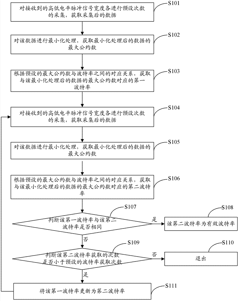
[0045] In the field of serial communication technology, the serial communication data format is as follows: 1 start bit, 8 data bits, 1 stop bit, and no parity bit. The start bit is always 0, the stop bit is always 1, and the level of the 8-bit data bit is determined by the transmitted data. To measure the baud rate of the data, as long as the transmission time of each bit of data is obtained, that is, the bit width of each bit of data. For example, the pulse width is counted by FPGA. When the crystal oscillator is 48M HZ and the data baud rate is 2400, 4800, 9600, 19200, 38400Baud, the corresponding transmission time per bit is about 26us~417us, and the corresponding count per bit width is 20000 , 10000, 5000, 2500, 1250, etc. In theory, regardless of the baud rate, the collected pulse width is an integer multiple of 1250.

[0046] figure 1 The implementation process of the serial communication baud rate identification method provided by the first embodiment of the present inv...

Embodiment 2

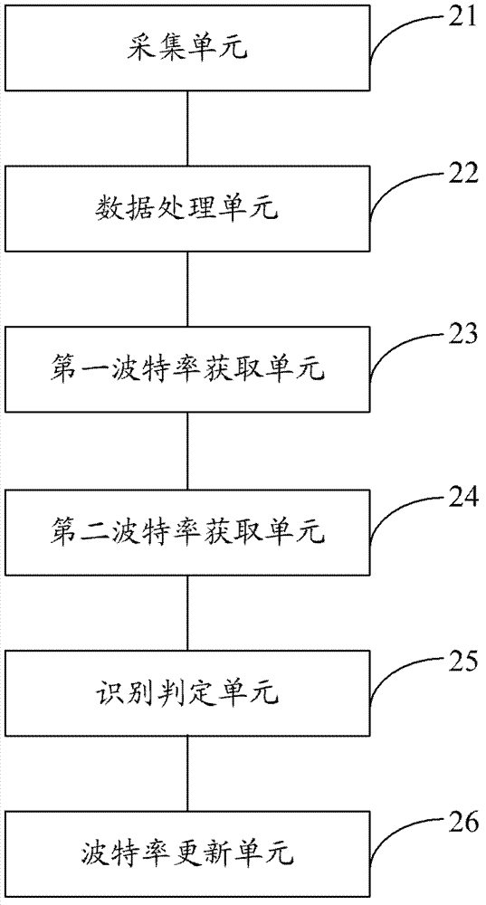
[0074] figure 2 The structure of the serial communication baud rate identification device provided by the second embodiment of the present invention is shown. For ease of description, only the parts related to the embodiment of the present invention are shown.

[0075] The serial communication baud rate recognition device can be used in monitoring equipment, or other security monitoring equipment with baud rate recognition function, such as high-speed dome cameras, etc., can be a software unit running in these monitoring equipment, or can be used as The independent pendant is integrated into these monitoring equipment or running in the application system of these monitoring equipment. The serial communication baud rate identification device includes an acquisition unit 21, a data processing unit 22, a first baud rate acquisition unit 23, and a second The baud rate acquisition unit 24, the identification determination unit 25 and the baud rate update unit 26, wherein:
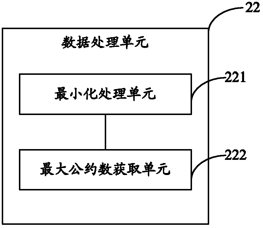
[0076] The ...


PUM


Abstract

The invention is applicable to the technical field of communication and provides a Baud rate identification method and device for serial communication and monitoring equipment. The method comprises the following steps: (1) carrying out width acquisition of preset times on received high-low level pulse signals respectively; (2) carrying out minimization on the acquired data, and obtaining the greatest common divisor of the minimized data; (3) obtaining a first Baud rate corresponding to the greatest common divisor according to the corresponding relationship between a preset greatest common divisor and a preset Baud rate; (4) re-executing the previous two steps, and obtaining a second Baud rate according to the corresponding relationship between the preset greatest common divisor and the preset Baud rate; and (5) when the first Baud rate is different from the second Baud rate and the number of acquisition times of the second Baud rate is less than that of the preset Baud rate, updating the first Baud rate to the second Baud rate, and returning to execute the step (4) until the first Baud rate and the obtained second Baud rate are the same. Thus, the flexibility and universality of the Baud rate identification method are improved.

Description

Technical field [0001] The invention belongs to the field of communication technology, and in particular relates to a serial communication baud rate identification method, device and monitoring equipment. Background technique [0002] In the field of security monitoring, the control of monitoring equipment is mainly realized through serial RS485 or RS422, which involves the setting of baud rate. Since the data of serial communication is transmitted in bit order, strict timing between each data bit is required to ensure correct communication. Only when the baud rate of the two communication parties is the same can the correct transmission and reception of data be realized. For example, in the front-end monitoring equipment (slave), such as fast dome and pan / tilt, there are special hardware dial codes for setting the baud rate of the front-end monitoring device, and different baud rates can be selected through the dial switch, such as The baud rate inside the dome and pan / tilt is ...

Claims


Application Information

Patent Timeline
IPC IPC(8): H04L12/26
Inventor 罗玮杰胡正文孔亚军
Owner SHENZHEN INFINOVA
Why Eureka
Try Eureka