Three-dimensional graphical lamina positioning method in magnetic resonance imaging and magnetic resonance imaging system

A magnetic resonance imaging and three-dimensional positioning technology, which is applied in medical science, sensors, diagnostic recording/measurement, etc., can solve the problems of unintuitive and difficult operation of graphical positioning methods, shorten the learning cycle, improve use efficiency, and be intuitive sexual effect

Active Publication Date: 2013-02-06
SHENZHEN UNITED IMAGING HEALTHCARE CO LTD
View PDF4 Cites 26 Cited by
  • Summary
  • Abstract
  • Description
  • Claims
  • Application Information

AI Technical Summary

Problems solved by technology

The present invention solves the disadvantages of the above-mentioned prior art graphical positioning method such as intuition and difficult operation, and proposes a three-dimensional graphical slice positioning method in magnetic resonance imaging, and innovatively introduces a three-dimensional positioning view into the magnetic resonance imaging system, It realizes information

Method used


Image

  • Three-dimensional graphical lamina positioning method in magnetic resonance imaging and magnetic resonance imaging system
  • Three-dimensional graphical lamina positioning method in magnetic resonance imaging and magnetic resonance imaging system
  • Three-dimensional graphical lamina positioning method in magnetic resonance imaging and magnetic resonance imaging system

Examples


Embodiment 1

[0067] This embodiment uses the magnetic resonance imaging system of the present invention to perform three-dimensional graphic slice positioning, and the process is as follows Figure 4 shown.

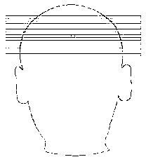
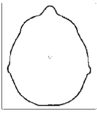
[0068] First, a two-dimensional localization image scan is performed on the detected target, and a two-dimensional reference image of one slice in the coronal plane, sagittal plane, and transverse plane is obtained.

[0069] The detected target is, for example, a certain part of the patient, which is the part of interest to the examiner, such as the brain. That is, when the examiner needs to know what pathological changes are in the patient's brain, he first performs a two-dimensional localization image scan of the patient's brain, and obtains two-dimensional images of one slice in the coronal plane, sagittal plane, and transverse plane of the brain. Reference image. As shown in Fig. 1, Fig. 1(a) is a 2D reference image of the coronal plane of the patient's brain, Fig. 1(b) is a 2D ...

Embodiment 2

[0083] In this embodiment, the positioning adjustment step is realized by the operator manipulating the slice graphic object in the three-dimensional positioning view, and other steps are similar to those in the first embodiment.

[0084] The positioning process is as Figure 5 As shown, the adjustment of the slice in the 3D localization view is immediately updated to the 2D reference image in the 2D localization view and displayed to the operator. At the same time, the adjustment of the slice in the 3D localization view is Changes to the positioning parameters are immediately updated in the parameter editor. The 2D positioning view, the 3D positioning view and the parameter editor are synchronized through the positioning parameters in the positioning protocol. Specifically, in the three-dimensional positioning view, the operator modifies the number of slices to 7, the thickness of slices to 1 mm, the position of slices to 2 mm toward the head, and the field of view to 200 × ...


PUM

PropertyMeasurementUnit
Thicknessaaaaaaaaaa

Abstract

The invention belongs to the field of magnetic resonance imaging, and particularly relates to a three-dimensional graphical lamina positioning method in magnetic resonance imaging. The three-dimensional graphical lamina positioning method comprises the following steps of: loading a two-dimensional reference image to a two-dimensional positioning view and visualizing the two-dimensional reference image in a three-dimensional positioning view; then displaying a lamina graphical object on the two-dimensional and three-dimensional positioning views; and timely updating adjustment in the two-dimensional or three-dimensional positioning view to the three-dimensional or two-dimensional positioning view, wherein positioning reference variation caused by the adjustment is also timely reflected on a parameter editor. The invention also provides a magnetic resonance imaging system. According to the three-dimensional graphical lamina positioning method in the magnetic resonance imaging and the magnetic resonance imaging system thereof, the position and the direction of the three-dimensional graphical object can be intuitively displayed and operated, what you see is what you get, the lamina positioning step is simplified, the operation difficulty is reduced, and the study period is shortened.

Description

technical field [0001] The invention belongs to the field of magnetic resonance imaging, and in particular relates to a three-dimensional graphic slice positioning method and a magnetic resonance imaging system in magnetic resonance imaging. Background technique [0002] Graphical slice positioning is a graphical interface based on reference images, which can visualize and define (manipulate) graphical objects such as slice groups, thick slice groups, saturation areas, volume calibration areas, etc. A series of parameters for setting the scan protocol. The positioning of the slice group and the thick slice group determines the image position and orientation of the scanned image, the saturation area is helpful for water-suppressed and fat-suppressed imaging, and the volume calibration area helps to obtain a uniform image and perform spectral imaging. In the prior art, the reference image is generally a scanned localization image or a series of images obtained by the same pat...

Claims


Application Information

Patent Timeline
IPC IPC(8): A61B5/055
Inventor 张强
Owner SHENZHEN UNITED IMAGING HEALTHCARE CO LTD
Why Eureka
Try Eureka