Vertical machining center main shaft box structure

A vertical machining center and spindle box technology, applied in metal processing equipment, metal processing mechanical parts, manufacturing tools, etc., can solve problems such as being unsuitable for low-speed heavy cutting and ignoring the low-speed cutting performance of products

Inactive Publication Date: 2013-02-06
SHANDONG LUNAN MACHINE TOOL
View PDF8 Cites 2 Cited by
  • Summary
  • Abstract
  • Description
  • Claims
  • Application Information

AI Technical Summary

Problems solved by technology

However, for some products, low-speed heavy cutting is required. The current headstock structure ignores the low-speed cutting performance of the product and is not suitable for low-speed heavy cutting.

Method used


Image

  • Vertical machining center main shaft box structure
  • Vertical machining center main shaft box structure

Examples


Embodiment Construction

[0016] The present invention will be further described below in conjunction with accompanying drawing and specific embodiment:

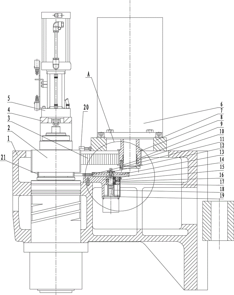
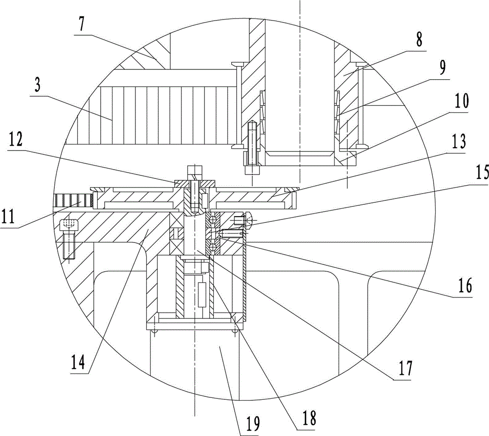
[0017] A spindle box structure of a vertical machining center, such as figure 1 and figure 2 As shown, it includes a main shaft housing 1. The main shaft housing 1 is equipped with a main shaft unit 2 and a main motor 6. The main shaft unit 2 includes a main shaft pulley, and the main motor 6 is connected to a main motor synchronous pulley 8. The synchronous pulley 8 is connected through the transmission of the first synchronous belt 3, and the transmission ratio between the main shaft pulley and the main motor synchronous pulley 8 is greater than 1:1; A transmission shaft 17 is installed for rotation, and one end of the transmission shaft 17 is connected with an encoder pulley 13, and the other end of the transmission shaft 17 is connected with an encoder coupling 18, and the encoder coupling 18 is connected with an encoder 19, and the encoder 19 ...


PUM


Abstract

The invention discloses a vertical machining center main shaft box structure which comprises a main shaft box body, wherein a main shaft unit and a main motor are arranged on the main shaft box body; the main shaft unit comprises a main shaft belt wheel; the main motor is connected with a main motor synchronous belt wheel; the main shaft belt wheel and the main motor synchronous belt wheel are in transmission connection by a first synchronous belt; the transmission ratio of the main shaft belt wheel and the main motor synchronous belt wheel is more than 1:1; an encoder base is fixedly arranged in the main shaft box body; a transmission shaft is relatively and rotationally arranged on the encoder base; one end of the transmission shaft is in transmission connection with an encoder belt wheel, while the other end of the transmission shaft is connected with an encoder shaft joint; the encoder shaft joint is connected with an encoder; the encoder is fixedly arranged on the encoder base; a belt wheel is arranged on the main shaft unit; the belt wheel and the encoder belt wheel are in transmission connection through a second synchronous belt; the transmission ratio of the belt wheel and the encoder belt wheel is 1:1; the main shaft unit is connected with a boosting cylinder through a boosting cylinder base; the main motor is arranged on the main shaft box body through a main motor seat plate; and one side of the main motor seat plate is connected with an adjusting block.

Description

technical field [0001] The invention relates to a spindle box, in particular to a spindle box structure of a vertical machining center. Background technique [0002] The structure of the existing spindle box of the vertical machining center is as follows: a spindle unit is arranged in the spindle box, a pressurized cylinder is arranged on the upper part of the spindle unit, and a tool is placed on the lower part of the spindle unit; the main motor synchronous pulley is installed on the spindle motor, and the main motor The pulley is connected with the main shaft unit through a timing belt. Generally, the transmission ratio of the main shaft pulley on the main shaft unit and the synchronous pulley of the main motor is 1:1. Since the main shaft unit rotates at a high speed (generally 6000-10000r / min), the tool speed is also relatively high, which is suitable for high speed processing. However, for some products, low-speed heavy cutting is required. The current headstock stru...

Claims


Application Information

Patent Timeline
Patent Type & Authority Applications(China)
IPC IPC(8): B23B19/00B23Q5/10
Inventor 王欣刘佳慧陈兆文邱伟张建玲
Owner SHANDONG LUNAN MACHINE TOOL
Why Eureka
Try Eureka