Spinning box

A spinning box and spinneret technology, which is applied in the field of chemical fiber filament machinery manufacturing, can solve the problems of low yarn output, low yarn efficiency, and restricted distribution of spinneret plate holes, so as to avoid filaments and breakage. head, improve production efficiency, eliminate the effect of flow dead center

Inactive Publication Date: 2013-02-06
ZHEJIANG HUATESI POLYMER TECHN
View PDF8 Cites 3 Cited by
  • Summary
  • Abstract
  • Description
  • Claims
  • Application Information

AI Technical Summary

Problems solved by technology

[0002] The spinning box in the prior art is generally a kind of spinning box disclosed in the invention patent application with the publication number CN1176320A; A spinning assembly capable of eliminating dead spots in melt flow disclosed in a patent application for invention includes an upper flow cover, an assembly cover, an assembly body, a sand cup and a spinneret, the sand cup is an annular sand cup, and the The inner cavity of the annular sand cup can be an annular inner cavity. The center of the annular sand cup is solid, and the annular cavity is filled with filter sand. However, the above-mentioned structure has restrictions on the distribution of the spinneret holes, just as the above-mentioned invention patent The spinneret described in the application only has plate holes in its outer ring and has only one ring, resulting in low efficiency of yarn production by this spinning assembly and low yarn yield

Method used


Image

  • Spinning box
  • Spinning box
  • Spinning box

Examples


Embodiment 1

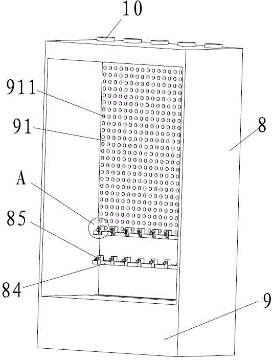
[0035] Embodiment 1: as Figure 1-8 As shown, a spinning box includes a frame 8, a yarn spray tank 10 positioned on the top of the frame 8, a blowing mechanism for blowing the yarn, a yarn guide assembly arranged between the two sides of the frame 8, and a Between the two sides of the frame 8 and the yarn drawing assembly below the yarn guiding assembly and the yarn collection box 9 below the frame 8 .

[0036] The blowing mechanism includes a fan, and a wind plate 91 communicating with the fan and having a plurality of air holes 911; the fan is not shown in the figure.

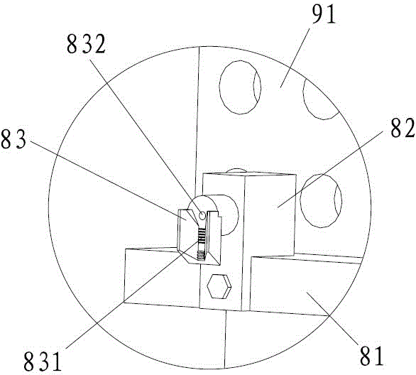
[0037] The yarn guide assembly includes a crosspiece 81 arranged between the two sides of the frame 8, a base 82 is arranged on the crosspiece 81, and a poly yarn that gathers a plurality of yarns and injects oil is fixed on the base 82. The thread-gathering piece 83 has a plurality of protrusions 831 distributed longitudinally in the middle of the wire-gathering piece 83, and an oil hole 832 for spraying oi...

Embodiment 2

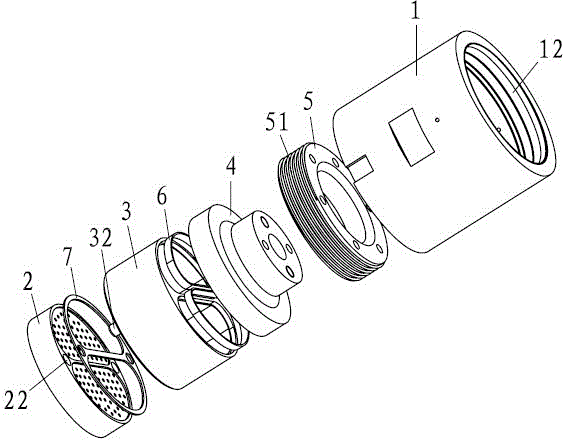
[0042] Embodiment 2: The difference with Embodiment 1 is that, as Figure 9-10 As shown, the height of the sealing ring is relatively large; there is no step on the upper inner wall of the flow channel 31 , and one end of the sealing ring is in contact with the filter plate 311 .

Embodiment 3

[0043] Embodiment 3: The difference with Embodiment 1 is that, as Figure 11 As shown, the diversion area 43 is provided with a groove 431 , the side wall of the groove 431 is on the same surface as the inner side wall of the diversion area 43 ; one end of the sealing ring is inserted into the groove 431 .


PUM


Abstract

The invention relates to mechanical manufacturing of chemical fiber filament, in particular to a spinning box. According to the invention, the spinning box is achieved by the following technical scheme: the spinning box comprises a frame, a yarn spraying tank, an air blowing mechanism, a yarn guide module, a yarn leading module and a yarn collecting box, wherein the yarn spraying tank is arranged at the upper part of the frame; the air blowing mechanism is used for blowing air to yarns; the yarn guide module is arranged between the two sides of the frame; the yarn leading module is arranged between the two sides of the frame and positioned below the yarn guide module; the yarn collecting box is arranged below the frame; the yarn spraying tank comprises a tank cylinder and a yarn spraying plate, a yarn cup and a fluid passing body, wherein the yarn spraying plates are mounted in the tank cylinder and are provided with at least two yarn spraying areas with a plurality of fine holes; the yarn cup is provided with fluid passages corresponding to the yarn spraying areas one to one; the fluid passing body is provided with a fluid inlet and provided with shunting passages, which are communicated with the fluid inlet and corresponding to the fluid passages one to one; and the bottom of each fluid passage is a filter plate with a plurality of micro holes. According to the invention, the yarn spraying tank has no flowing dead point so that broken filaments and broken ends are prevented; moreover, as high yarn yield is obtained, the spinning box provided by the invention is beneficial for increasing production efficiency.

Description

technical field [0001] The invention relates to the mechanical manufacture of chemical fiber filaments, in particular to a spinning box. Background technique [0002] The spinning box in the prior art is generally a kind of spinning box disclosed in the invention patent application with the publication number CN1176320A; A spinning assembly capable of eliminating dead spots in melt flow disclosed in a patent application for invention includes an upper flow cover, an assembly cover, an assembly body, a sand cup and a spinneret, the sand cup is an annular sand cup, and the The inner cavity of the annular sand cup can be an annular inner cavity. The center of the annular sand cup is solid, and the annular cavity is filled with filter sand. However, the above-mentioned structure has restrictions on the distribution of the spinneret holes, just as the above-mentioned invention patent The spinneret described in the application only has plate holes in its outer ring and has only o...

Claims


Application Information

Patent Timeline
Patent Type & Authority Applications(China)
IPC IPC(8): D01D13/02D01D4/06
Inventor 戚海栋
Owner ZHEJIANG HUATESI POLYMER TECHN
Why Eureka
Try Eureka