
Sound wave soot blower

The technology of a sonic soot blower and a soot blowing tube is applied in the field of soot blowing devices, which can solve problems such as affecting furnace efficiency and hidden dangers of safe operation of a heating furnace, and achieve the effects of wide soot blowing range and low cost.

Inactive Publication Date: 2013-02-06
SHAANXI QIYUAN TECH DEV
View PDF0 Cites 4 Cited by
  • Summary
  • Abstract
  • Description
  • Claims
  • Application Information

AI Technical Summary

Problems solved by technology

[0002] Most of the sootblowers currently used on direct tube heating furnaces are pneumatic rotary sootblowers. This kind of sootblower can blow the soot out of the furnace with the airflow, but the soot is easy to form coking and scaling on the heating furnace tube, not only The capacity will affect the furnace efficiency, and will also cause hidden dangers to the safe operation of the heating furnace

Method used


Image

  • Sound wave soot blower

Examples


Embodiment 1

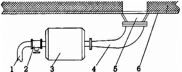
[0011] A sonic soot blower according to the present invention comprises a compressed air pipe 1, a control valve 2, a sound wave generating device 3, a sound conduit 4 and a soot blowing pipe 5 connected in sequence, the control valve 2 is opened, and the compressed air passes through the compressed air pipe 1 enters the sound wave generator 3, and the sound wave is emitted by the sound wave generator 3. The sound wave is amplified by the sound guide 4 and then enters the soot blowing pipe 5, and the soot blowing pipe 5 is deep into the heating furnace wall plate 6 for purging. The sound wave energy can make the area The air molecules in the furnace and the dust particles oscillate, and under the action of repeated vibrations of the sound waves, the cyclic variable load and cyclic stress of the ash accumulation in the furnace also act repeatedly, destroying the combination of the dust particles, the heat exchange surface and the particles. Coupled with the collision between...


PUM


Abstract

The invention provides a sound wave soot blower and relates to a soot blower applied to a heating furnace. The sound wave soot blower comprises a compressed air pipe, a sound wave generating device, a sound conduit and a soot blowing pipe which are sequentially connected with one another. The sound wave soot blower is wide in soot blowing range, avoids dead angle and dead zone, prevents soot from coking and scaling in the heating furnace, is simple and practical, has low cost and can perform industrialized production.

Description

technical field [0001] The invention relates to a soot blowing device used in a heating furnace. Background technique [0002] Most of the sootblowers currently used on direct tube heating furnaces are pneumatic rotary sootblowers. This kind of sootblower can blow the soot out of the furnace with the airflow, but the soot is easy to form coking and scaling on the heating furnace tube, not only The capacity affects the furnace efficiency, and will also cause hidden dangers to the safe operation of the heating furnace. Contents of the invention [0003] The present invention aims at proposing a sonic sootblower which does not form coke on the furnace. [0004] A sonic soot blower proposed by the present invention is characterized in that it includes a compressed air pipe, a sound wave generating device, a sound conduit, and a soot blowing pipe, and the compressed air pipe, the sound wave generating device, the sound conduit, and the soot blowing pipe are connected in sequen...

Claims


Application Information

Patent Timeline
IPC IPC(8): F23J1/00F23J3/00
Inventor 张淑芬
Owner SHAANXI QIYUAN TECH DEV
Learn More