Refrigerant distributing device and parallel flow heat exchanger

A technology of diverting device and refrigerant, applied in the direction of evaporator/condenser, refrigerator, refrigeration components, etc., can solve the problems of partial flow of heat exchanger, low heat exchange efficiency, large difference in refrigerant, etc., and achieve the effect of improving heat exchange efficiency

Active Publication Date: 2013-02-06
GD MIDEA AIR-CONDITIONING EQUIP CO LTD
View PDF6 Cites 13 Cited by
  • Summary
  • Abstract
  • Description
  • Claims
  • Application Information

AI Technical Summary

Problems solved by technology

At present, the technology of parallel flow heat exchanger applied to the outdoor condenser of single-cooling air conditioner has become mature. When the parallel flow heat exchanger is used as an evaporator, since the refrigerant in the input header is in a gas-liquid two-phase state, and the refrigerant needs Multiple flat tubes are distributed to the input header at the same time, and the header is longer, and the number of corresponding plaque tubes is large, so that the refrigerant distributed by each flat tube is quite different, which leads to the deviation of the entire heat exchanger thermal inefficiency

Method used


Image

  • Refrigerant distributing device and parallel flow heat exchanger
  • Refrigerant distributing device and parallel flow heat exchanger
  • Refrigerant distributing device and parallel flow heat exchanger

Examples


Embodiment Construction

[0017] It should be understood that the specific embodiments described here are only used to explain the present invention, not to limit the present invention.

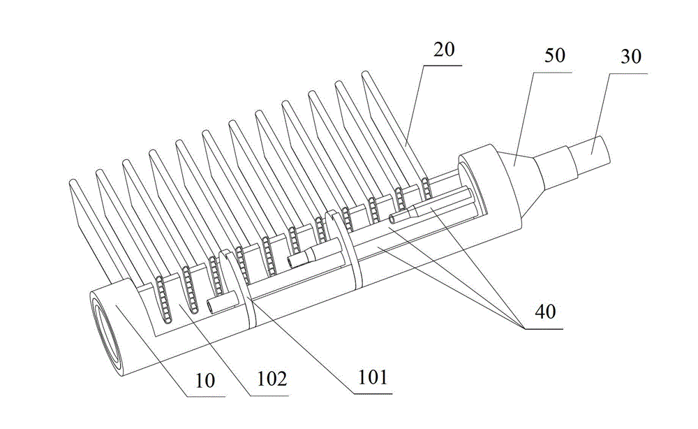
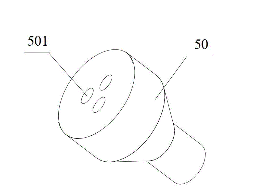
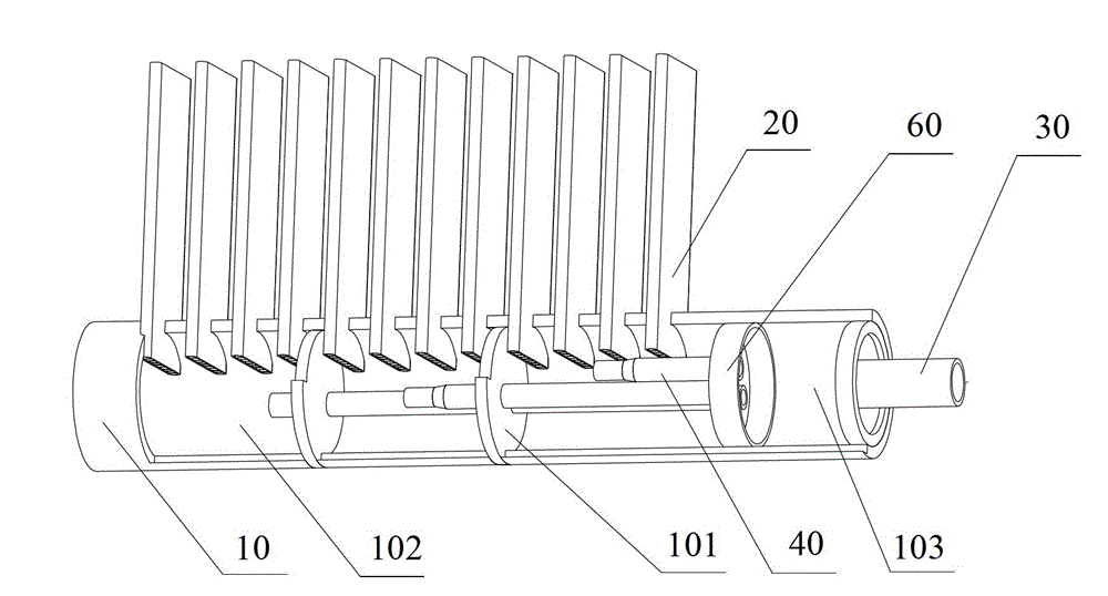
[0018] refer to figure 1 and figure 2 as shown, figure 1 It is a schematic structural diagram of the first embodiment of the refrigerant distribution device of the present invention, figure 2 for figure 1 Schematic diagram of the distributor structure. The refrigerant distribution device provided in this embodiment includes a header 10, a flat pipe 20 communicating with the header 10, and an input pipe 30 for inputting refrigerant. The flow tube 10 is divided to form a plurality of chambers 102 , each chamber 102 communicates with a plurality of flat tubes 20 , and each chamber 102 communicates with the input pipe 30 through the connection pipe 40 .

[0019] In this embodiment, a connecting pipe 40 can be arranged in each of the above-mentioned chambers 102 correspondingly, and the connecting pipe 40 passes thr...


PUM


Abstract

The invention discloses a refrigerant distributing device which comprises a collecting pipe, flat pipes and an input pipe, wherein the flat pipes are communicated with the collecting pipe, and the input pipe is used for inputting refrigerants. At least one partition is arranged in the collecting pipe, the collecting pipe is partitioned into a plurality of chambers by the partitions, and the chambers are communicated with the flat pipes and are communicated with the input pipe through connecting pipes respectively. The invention further provides a parallel flow heat exchanger with the refrigerant distributing device. By the aid of the refrigerant distributing device, heat exchange efficiency of the heat exchanger can be improved.

Description

technical field [0001] The invention relates to the technical field of air conditioning, in particular to a refrigerant flow splitting device and a parallel flow heat exchanger. Background technique [0002] In recent years, in order to meet the demand for low energy consumption, most air-conditioning manufacturers have adopted micro-channel parallel flow heat exchangers to replace the traditional copper tube-fin heat exchangers in household air conditioners, so as to achieve high energy efficiency of air conditioners. At the same time reduce the cost of air conditioners. At present, the technology of parallel flow heat exchanger applied to the outdoor condenser of single-cooling air conditioner has become mature. When the parallel flow heat exchanger is used as an evaporator, since the refrigerant in the input header is in a gas-liquid two-phase state, and the refrigerant needs Multiple flat tubes are distributed to the input header at the same time, and the header is long...

Claims


Application Information

Patent Timeline
Patent Type & Authority Applications(China)
IPC IPC(8): F25B41/00F25B39/00
Inventor 张智冬程志明
Owner GD MIDEA AIR-CONDITIONING EQUIP CO LTD
Why Eureka
Try Eureka