Novel denitration nozzle base, multinozzle denitration spray gun barrel and denitration spray gun
A multi-nozzle and nozzle technology, applied in multi-nozzle denitrification spray gun shaft and denitrification spray gun, new denitrification nozzle base field, can solve the problems of low denitration efficiency and poor denitration effect, achieve uniform fluid atomization, consistent flow rate, and improved denitrification efficiency Effect
- Summary
- Abstract
- Description
- Claims
- Application Information
AI Technical Summary
Problems solved by technology
Method used
Image
Examples
Embodiment 1
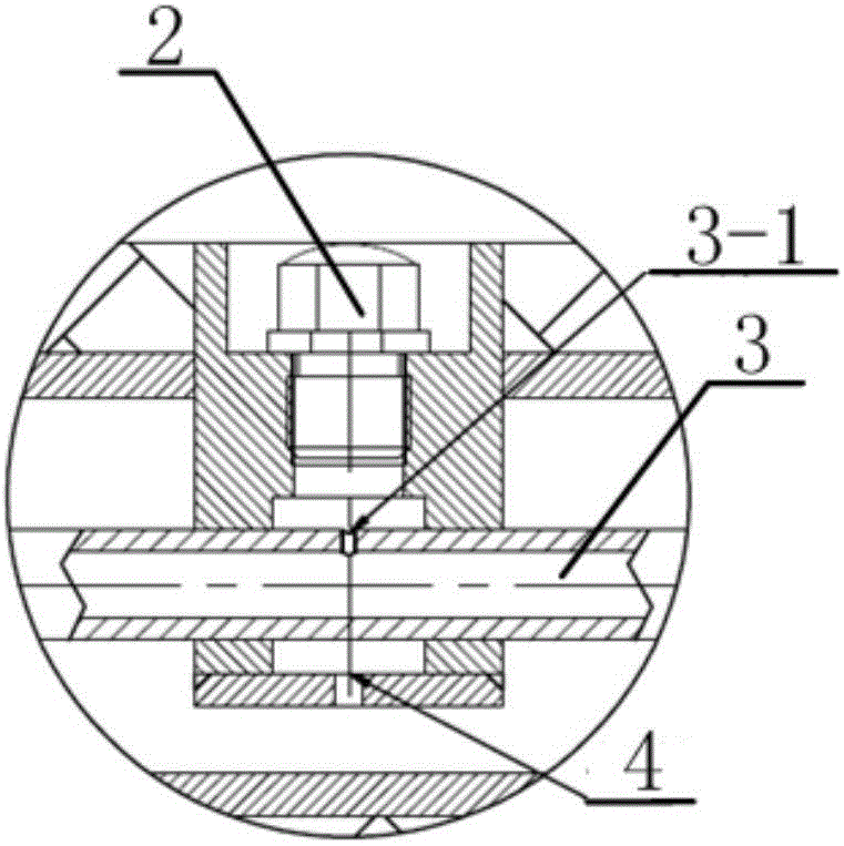
[0044] figure 1 It is a schematic structural diagram of a new denitration nozzle base shown in an embodiment of the present invention, including a nozzle base 1, a nozzle 2, a liquid pipe 3, and an air inlet 4, wherein,
[0045] The nozzle base 1 is provided with a cavity with an open end;
[0046] The nozzle 2 is sealed and arranged at the opening of the cavity, and the through hole in the nozzle 2 communicates with the space in the cavity;
[0047] The liquid pipe 3 runs through the cavity of the nozzle base 1, and the liquid pipe 3 and the nozzle base 1 are sealed;
[0048] The liquid pipe 3 is provided with a through hole 3-1 on the outer wall of the cavity of the nozzle base 1, and the through hole 3-1 communicates with the cavity of the nozzle base 1;
[0049] The bottom end of the nozzle base 1 is provided with an air inlet 4 , and the air inlet 4 communicates with the inner space of the liquid pipe 3 passing through the cavity of the nozzle base 1 .
[0050] Prefera...
Embodiment 2
[0055] figure 2 It is a structural schematic diagram of a denitrification spray gun provided by the present invention, including a multi-nozzle denitrification spray gun shaft, and the denitrification spray gun shaft includes several nozzle bases 1 as described in Example 1, a gas-liquid distribution body 5, and a liquid pipe 3 , the first casing 6, wherein,
[0056] The several nozzle bases 1 are sequentially sealed and connected along the horizontal direction, and the internal spaces communicate with each other;
[0057] The gas-liquid distribution body 5 includes a reducing agent inlet 5-1 and a compressed air inlet 5-2;
[0058] The first sleeve 6 is arranged outside the liquid pipe 3;
[0059] The reducing agent inlet 5-1 is sealedly connected to the left end of the liquid pipe 3 through the liquid flow pipe 5-3 provided in the horizontal direction of the gas-liquid distribution body 5, and the internal space communicates with each other;
[0060] The compressed air i...
Embodiment 3
[0064] figure 2 It is a structural schematic diagram of a denitrification spray gun provided by the present invention. The denitration spray gun includes a gas-liquid distribution body 5 arranged in sequence, and a liquid that is sealed and connected with a liquid flow pipe 5-3 arranged in the horizontal direction of the gas-liquid distribution body 5. Pipe 3, the first casing 6 arranged on the outside of the liquid pipe 3, the liquid pipe 3 is provided with a nozzle base 1, and the nozzle base 1 is equipped with a nozzle 2; wherein,
[0065] The gas flow pipe 5-4 arranged in the horizontal direction of the gas-liquid distribution body 5 is sealedly connected with the left end of the first sleeve 6 and the internal space communicates with each other;
[0066] The nozzle base 1 is provided with a cavity with an open end;
[0067] The nozzle 2 is sealed and arranged at the opening of the cavity, and the nozzle 2 communicates with the space in the cavity;
[0068] The liquid p...
PUM
 Abstract
Description
Claims
Application Information
 - R&D
- Intellectual Property
- Life Sciences
- Materials
- Tech Scout
- Unparalleled Data Quality
- Higher Quality Content
- 60% Fewer Hallucinations
Browse by: Latest US Patents, China's latest patents, Technical Efficacy Thesaurus, Application Domain, Technology Topic, Popular Technical Reports.
© 2025 PatSnap. All rights reserved.Legal|Privacy policy|Modern Slavery Act Transparency Statement|Sitemap|About US| Contact US: help@patsnap.com


