Tool wear automatic compensation method and system, and corresponding numerically-controlled machine tool machining equipment

A technology of automatic compensation and tool wear, applied in general control systems, control/regulation systems, program control, etc., can solve problems such as time-consuming and high operator requirements, and achieve the effect of avoiding time-consuming

Inactive Publication Date: 2013-02-06
SHENZHEN LUNGMA CNC EQUIP
View PDF2 Cites 31 Cited by
  • Summary
  • Abstract
  • Description
  • Claims
  • Application Information

AI Technical Summary

Problems solved by technology

[0005] The technical problem to be solved by the present invention is that it is time-consuming to set tool compensation for CNC machine tool processing equipment in the prior art, and at the same time, it has high

Method used


Image

  • Tool wear automatic compensation method and system, and corresponding numerically-controlled machine tool machining equipment
  • Tool wear automatic compensation method and system, and corresponding numerically-controlled machine tool machining equipment
  • Tool wear automatic compensation method and system, and corresponding numerically-controlled machine tool machining equipment

Examples


Embodiment Construction

[0029] In order to make the object, technical solution and advantages of the present invention clearer, the present invention will be further described in detail below in conjunction with the accompanying drawings and embodiments. It should be understood that the specific embodiments described here are only used to explain the present invention, not to limit the present invention.

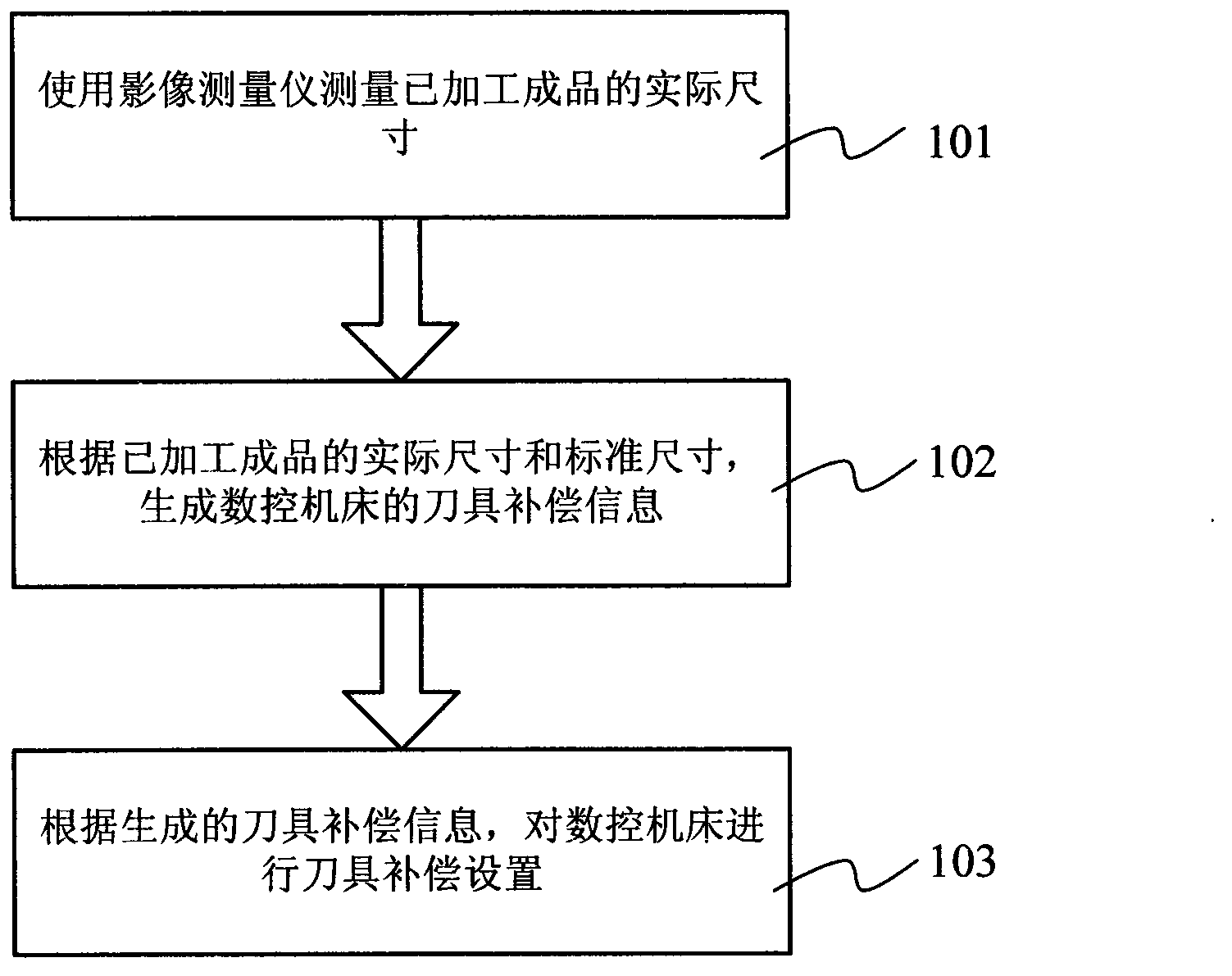
[0030] Please refer to figure 1 , figure 1 It is a flowchart of a preferred embodiment of the automatic tool wear compensation method of the present invention. This automatic tool wear compensation method starts with:

[0031] Step 101, using a video measuring instrument to measure the actual size of the finished product;

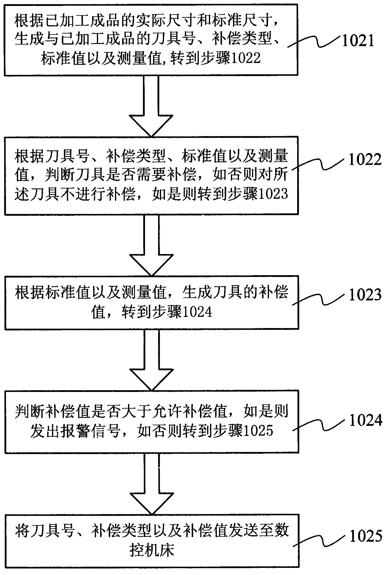
[0032] Step 102, generating tool compensation information for the CNC machine tool according to the actual size and standard size of the processed finished product;

[0033] Step 103, according to the generated tool compensation information, perform tool compensation setting...


PUM


Abstract

The invention relates to a tool wear automatic compensation method and system, and corresponding numerically-controlled machine tool machining equipment. The method comprises the following steps of: A, measuring actual size of a finished product by an image measuring instrument; B, obtaining tool compensation information of the numerically-controlled machine tool based on the actual size and standard size of the finished product; and C, carrying out the tool compensation to the numerically-controlled machine tool based on the tool compensation information. The tool wear automatic compensation method and system, and the corresponding numerically-controlled machine tool machining equipment provided by the invention can carry out the tool compensation automatically, save time and labor, and avoid the defects that the existing tool compensation method and system is time-consuming when the tool compensation is carried out and the requirement to the operators is high.

Description

technical field [0001] The invention relates to the field of computer detection and control, and more specifically relates to a tool wear automatic compensation method, system and corresponding numerical control machine tool processing equipment. Background technique [0002] In the existing glass processing process, the cutting tools used for processing will inevitably wear out gradually. When the tool is worn out, its size will change. At this time, it is necessary to modify the processing parameters of the tool in the controller of the processing system, otherwise it will affect the processing accuracy of the workpiece. [0003] The existing tool wear compensation method is: the operator puts the processed glass on the image measuring instrument, and the image measuring instrument is a device that obtains the image of the measured object through a CCD (Charge-coupled Device, charge-coupled device) for size measurement. The image measuring instrument will check whether th...

Claims


Application Information

Patent Timeline
IPC IPC(8): G05B19/404
Inventor 常俊勇
Owner SHENZHEN LUNGMA CNC EQUIP
Why Eureka
Try Eureka