
Safety structure of a power battery pack

A power battery pack and safety structure technology, applied to battery pack parts, structural parts, circuits, etc., can solve problems such as temperature rise of faulty batteries, explosion of faulty batteries, hidden dangers of normal operation of battery packs, etc., to ensure anti-vibration capability , preventing proliferation and protecting safety

Active Publication Date: 2016-03-02
OPTIMUM BATTERY CO LTD
View PDF6 Cites 0 Cited by
  • Summary
  • Abstract
  • Description
  • Claims
  • Application Information

AI Technical Summary

Problems solved by technology

However, it is difficult to balance the battery pack in the first series and then parallel scheme
Adding a parallel branch in the same row of single cells can play a balanced role to a certain extent, but this brings another problem, that is, when a short circuit occurs inside a single cell, the short circuit between the single cell and the single cell All the single batteries connected in parallel are short-circuited externally, and the energy of all the batteries connected in parallel is quickly released in the faulty single battery, and the temperature of the faulty battery rises sharply, which may cause the faulty battery to explode, and finally destroy the normal operation of the entire battery pack. Work leaves a huge safety hazard
[0005] In addition, electric vehicles and electric buses may experience violent bumps during driving, and the battery packs installed in the existing power boxes that are composed of several lithium iron phosphate batteries in series and parallel are usually not designed for shock resistance

Method used


Image

  • Safety structure of a power battery pack
  • Safety structure of a power battery pack
  • Safety structure of a power battery pack

Examples


Embodiment Construction

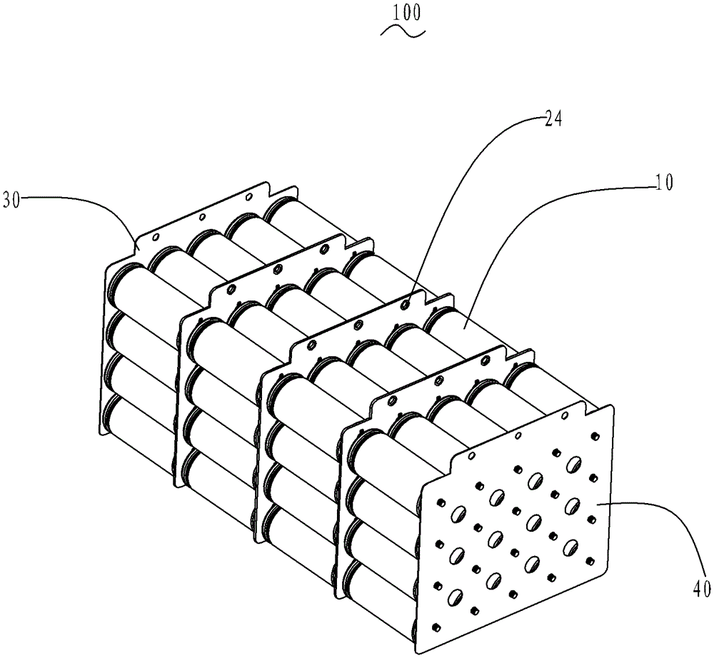
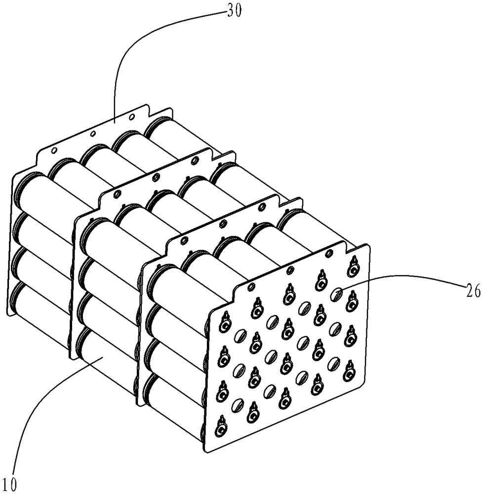
[0023] Please refer to Figure 1 to Figure 4 As shown, the present invention is a safety structure of a power battery pack. The battery pack 100 includes M layers of single cells 10 arranged in an N×P matrix, and each adjacent two layers of single cells 10 are correspondingly connected in series. A reinforced circuit board 20 is connected between every two adjacent layers of single cells 10 , and the electrodes of the topmost and bottommost single cells of the battery pack 100 are respectively connected to the general positive plate 30 and the general negative plate 40 .

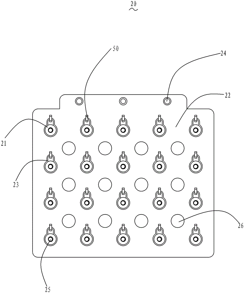
[0024] The reinforced circuit board 20 is roughly rectangular, and includes N×P electrode connection pieces 21 for connecting the polarity of the single battery 10 (the polarity can be divided into positive and negative), and a conductive main board 22 for insulating and isolating the electrodes. The connecting sheet 21 and the insulator 23 of the conductive main board 22 . The tops of the reinforced circui...


PUM

PropertyMeasurementUnit
currentaaaaaaaaaa

Abstract

The invention discloses a safety structure for a power battery pack. The power pack comprises M layers of single batteries arranged in an N*P matrix manner, wherein every adjacent two layers of single batteries are correspondingly connected in series, a reinforced circuit board is connected between every two adjacent two layers of single batteries, the reinforced circuit board comprises N*P electrode connecting pieces for connecting the polarities of the single batteries, a conducting main board, and an insulator used for isolating the electrode connecting pieces and the conducting main board in an insulation manner, and a safety device with the two ends respectively and electrically connected with the conducting main board and the electrode connecting pieces is arranged on each reinforced circuit board. Compared with the prior art, the reinforced circuit boards are additionally arranged, so that the quake-proof capability of the battery pack is guaranteed, and on the other hand, if a single battery in the battery pack is short-circuited, a fuse on the reinforced circuit board is blown, the diffusion of the failure single battery is prevented, and the safety of the battery pack is protected.

Description

【Technical field】 [0001] The invention relates to the technical field of safety of power battery packs, in particular to a safety structure of power battery packs suitable for electric vehicles and electric buses. 【Background technique】 [0002] As a new type of lithium battery, lithium iron phosphate battery represents the future direction of battery development. It is the most ideal power battery invented so far. The lithium iron phosphate battery industry is in line with the orientation of the national industrial policy. All countries put its development at the national strategic level, and the supporting funds and policy support are very strong. [0003] As a new energy source for automobiles, lithium iron phosphate batteries have been widely used. However, electric vehicles and electric buses have relatively high requirements on battery voltage and current. Therefore, the power boxes of electric vehicles and electric buses are equipped with battery packs composed of se...

Claims


Application Information

Patent Timeline
Patent Type & Authority Patents(China)
IPC IPC(8): H01M2/34
CPCY02E60/10
Inventor 耿德先
Owner OPTIMUM BATTERY CO LTD
Learn More