Cutting torch lifting mechanism of cutting machine

A cutting machine and cutting torch technology, applied in the field of industrial cutting equipment, can solve the problems of no anti-collision device, high cost, affecting the quality of cutting, etc., and achieve the effect of reducing design cost and compact overall structure

Inactive Publication Date: 2013-02-13
WUXI YANGTONG MACHINERY EQUIP
View PDF0 Cites 3 Cited by
  • Summary
  • Abstract
  • Description
  • Claims
  • Application Information

AI Technical Summary

Problems solved by technology

[0007] 2. The existing technology does not have an anti-collision device, and the lifting mec

Method used


Image

  • Cutting torch lifting mechanism of cutting machine
  • Cutting torch lifting mechanism of cutting machine

Examples


Example Embodiment

[0026] The present invention will be further described below in conjunction with the accompanying drawings, but the protection scope of the present invention is not limited to the scope expressed by the specific embodiments.

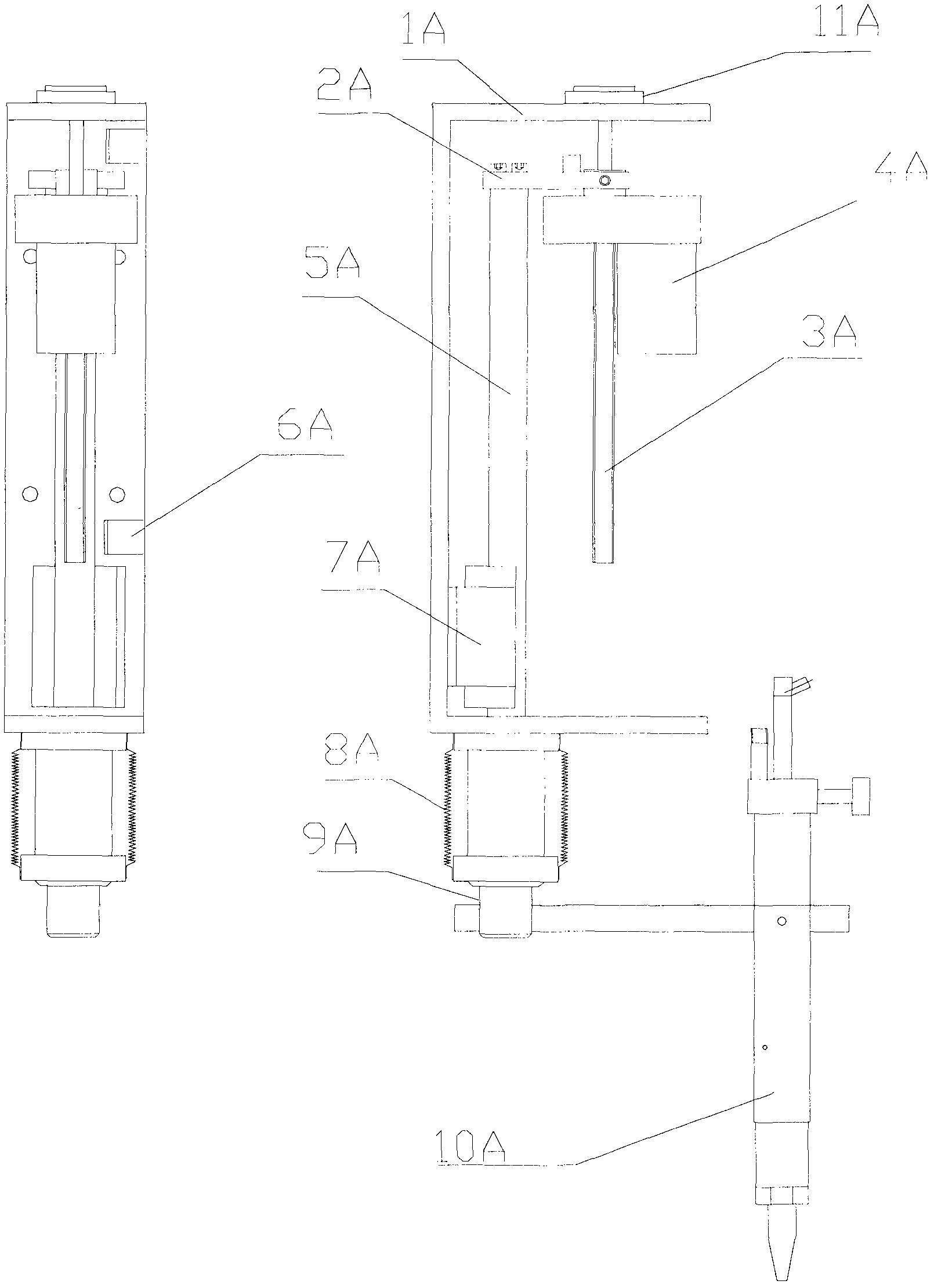
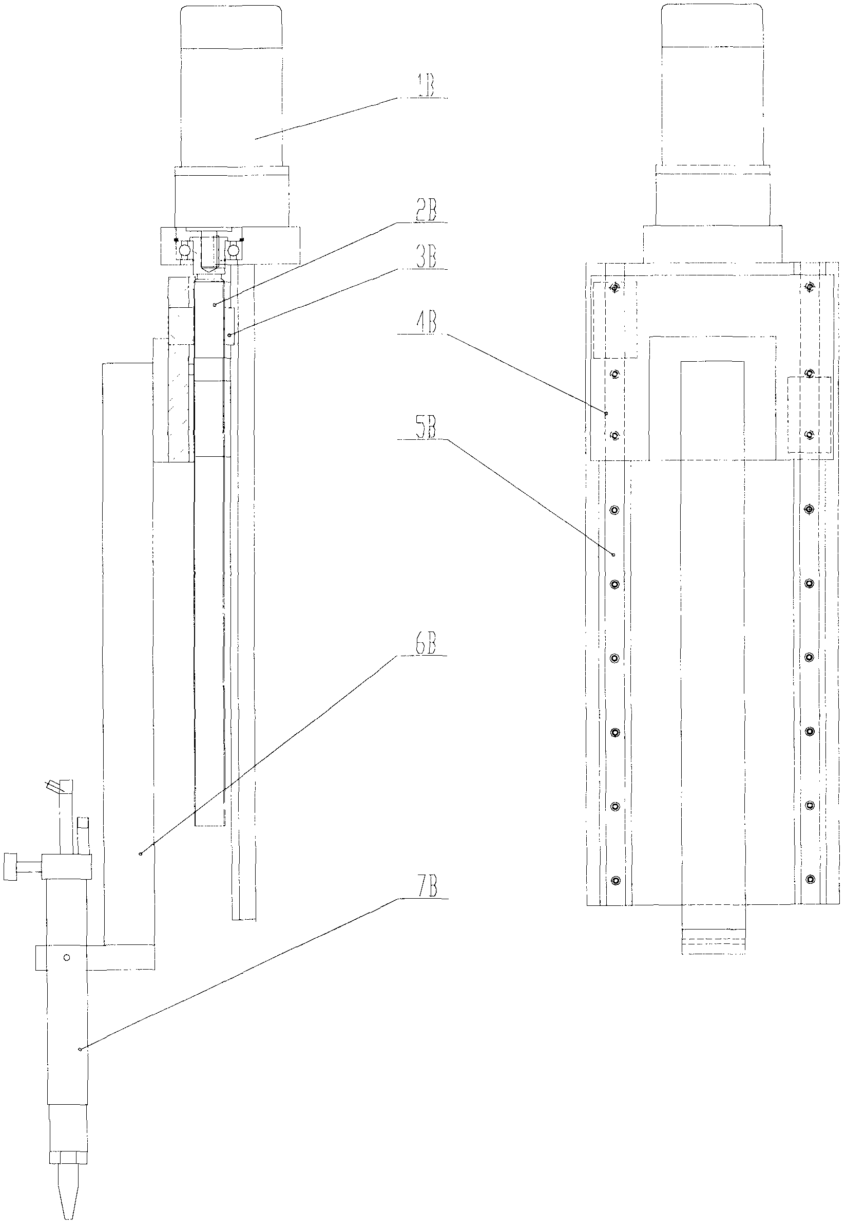
[0027] Cutting machine torch lifting mechanism, including frame 1A, connecting plate 2A, screw rod 3A, driving device 4A, linear guide rail 5A, guide rail slider 7A, telescopic dust cover 8A, transition rod 9A and cutting torch 10A.

[0028] Among them, the connection plate 2A, the screw rod 3A, the driving device 4A, the linear guide rail 5A, the telescopic dust cover 8A, the transition rod 9A and the cutting torch 10A are not connected with the frame 1A;

[0029] The screw mandrel 3A passes through the driving device 4A, the connecting plate 2A and the frame 1A sequentially from bottom to top, and the end of the screw mandrel 3A with an elastic washer 11A is suspended on the frame 1A; the driving device 4A and the The connecting plate 2A is connected a...


PUM


Abstract

The invention relates to a cutting torch lifting mechanism of a cutting machine. The cutting torch lifting mechanism comprises a frame, a connecting plate, a screw rod, a speed reducer, a linear guide rail, a telescopic dustproof cover, a transitional rod and a cutting torch, wherein the parts are not connected with the frame; the upper end of the screw rod is mounted with a gasket; the lower end of the screw rod penetrates through the frame and is suspended on the frame; the driving device is connected to the screw rod; one end of the connecting plate is connected with the driving device; the other end of the connecting plate is connected with the upper end of the linear guide rail; the lower end of the guide rail penetrates through the bottom of the frame; a guide rail slide bock is mounted at the bottom of the longitudinal inner wall of the frame; the lower end of the guide rail is connected with one end of the transitional rod; the other end of the transitional rod is connected with the cutting torch; the telescopic dustproof cover is sleeved outside the linear guide rail outside the frame; and travel limiters are arranged at upper and lower ends of the longitudinal inner wall of the frame. The cutting torch lifting mechanism of the cutting machine, provided by the invention, has the advantages of small structure, low cost, anti-collision performance, convenience in operation and greater safety and reliability in use and can be manually adjusted; a cutting nozzle and other parts of the cutting torch can be protected; the cutting quality is improved; and the lifting precision and stability are guaranteed.

Description

technical field [0001] The invention relates to an industrial cutting device, in particular to a cutting torch lifting mechanism of a cutting machine. technical background [0002] In today's industrial field, welded structural parts have been widely used in various industries. Plate cutting is the first step in the process of welding finished products, and it is also an important process to ensure the quality of welding. The use of advanced modern cutting technology can not only ensure the welding quality of products and improve labor productivity, but also greatly reduce the manufacturing cost of enterprise products and shorten the product production cycle. With the wide application of new products, new processes and new technologies. Intelligent precision cutting will become the future development trend of the cutting industry. Intelligent precision cutting technology can not only ensure the welding quality of products and improve labor productivity, but also greatly r...

Claims


Application Information

Patent Timeline
IPC IPC(8): B23K7/10B23K7/00
Inventor 曹东风薛金锴唐国强
Owner WUXI YANGTONG MACHINERY EQUIP
Why Eureka
Try Eureka