Chemical mechanical polishing method

A grinding method and chemical-mechanical technology, used in grinding devices, grinding machine tools, electrical components, etc., can solve the problems of insufficient grinding, no way to effectively grind, over-grinding, etc.

Active Publication Date: 2013-02-13
CSMC TECH FAB2 CO LTD
View PDF7 Cites 5 Cited by
  • Summary
  • Abstract
  • Description
  • Claims
  • Application Information

AI Technical Summary

Problems solved by technology

In order to simplify the process, the grinding pads used in the whole grinding process at the factory end often have the same surface shape, and at the same time, for reasons of mechanical control, the grinding head will move on the two grinding pads with the same movement method and movement path. Grinding, this method will have some negative effects on the grinding effect, because during a grinding process of the wafer, it is inevitable that there will be areas of enhanced grinding in some areas of the wafer surface, while are...

Method used


Image

  • Chemical mechanical polishing method
  • Chemical mechanical polishing method
  • Chemical mechanical polishing method

Examples


Embodiment 1

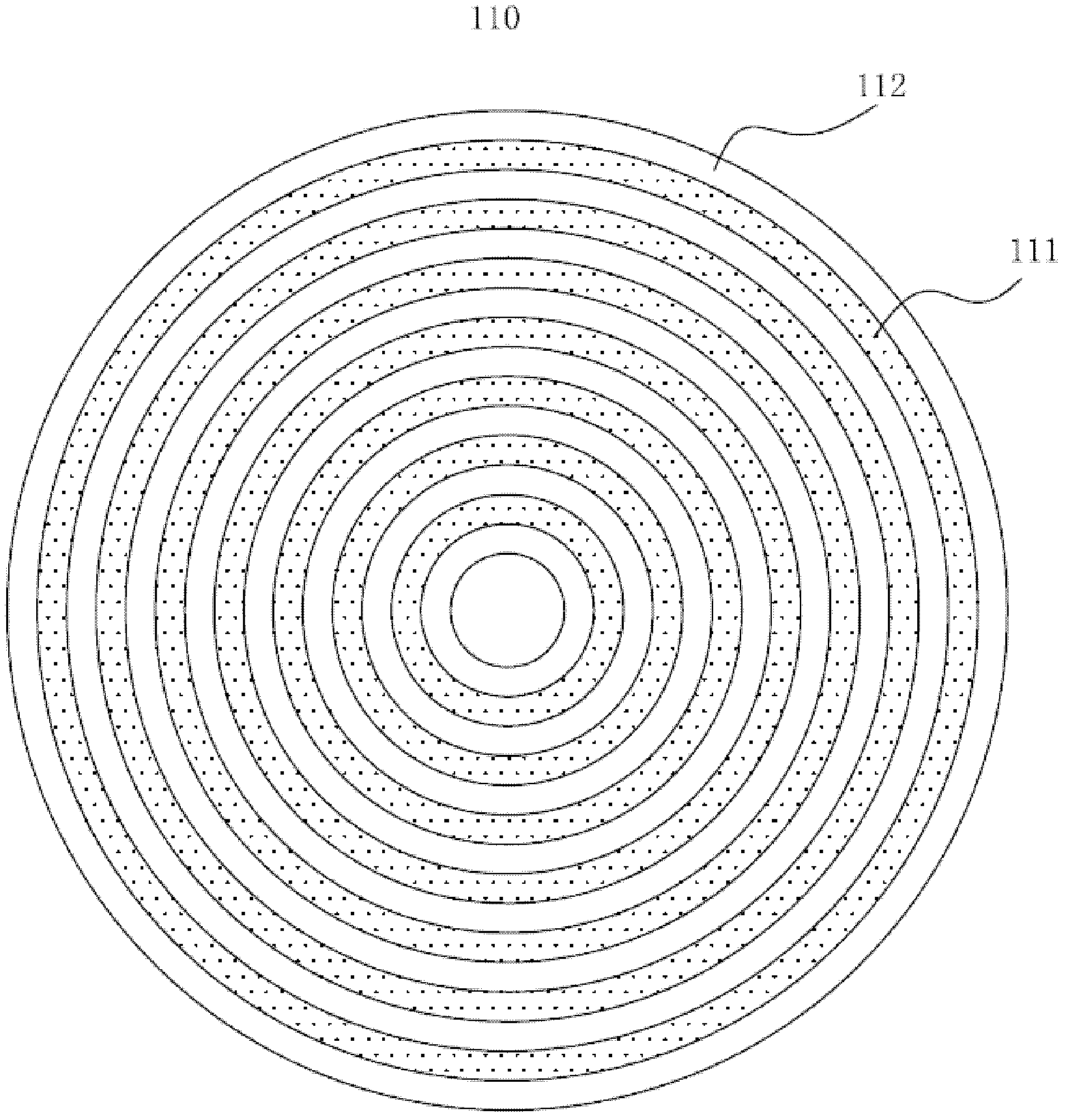
[0051] Embodiment 1 illustrates the chemical mechanical polishing method of the present invention using the same polishing pad and different polishing paths. The polishing pad used is a polishing pad with a concentric circle structure.

[0052] Please refer to Figure 3A-3B , Figure 3A-3B It is an existing concentric circle structure polishing pad. As shown in the figure, a plurality of concentric grooves 111 and convex islands 112 are arranged on the surface of the polishing pad 110 , and the grooves 111 and the convex islands 112 are arranged on the polishing pad 110 at intervals. Through these grooves 111, the distribution of the grinding liquid on the grinding pad 110, the flow of fresh grinding liquid in the grinding area, the flow of used grinding liquid out of the grinding area and the substantially unused grinding liquid flowing through the grinding area can be improved. The specific gravity of the grinding liquid, etc.

[0053] Specifically, taking grinding an 8-i...

Embodiment 2

[0065] Embodiment 2 is a chemical mechanical polishing method using two different polishing pads and the same or different polishing paths. The second embodiment is essentially a modification of the first embodiment. That is, the distribution of grooves and convex islands in the first grinding pad 210 and the second grinding pad 210' is just opposite. On the first grinding pad 210, it is the position of the grooves, and on the second grinding pad 210', it happens to be convex islands. On the first polishing pad 210 are convex islands, and on the second polishing pad 210' are exactly grooves. Such as Figure 8 as shown, Figure 8 It is a comparison diagram of polishing pads with two different surface structures in Example 2. In this case, even if the trajectories of the first grinding path and the second grinding path are not changed, the resulting grinding effect can play a complementary role.

[0066] Further, if the changes of grooves and convex islands are not only diff...


PUM


Abstract

The invention provides a chemical mechanical polishing method; the chemical mechanical polishing method comprises the step of respectively executing polishing in different stages on two polishing pads, wherein through using surface structures of the two polishing pads or changing polishing paths in the different stages, a first polishing effect of the polishing in the first stage on wafer surface is complementary to a second polishing effect of the polishing in the second stage on the wafer surface; therefore, a polishing weakening area is formed in the second polishing stage if a polishing reinforcing area is formed in the first polishing stage, and a polishing reinforcing area is formed in the second stage if a polishing weakening area is formed in the first stage. Therefore, polishing amounts are uniformly distributed and excessive polishing or insufficient polishing phenomenon is avoided.

Description

technical field [0001] The invention relates to the technical field of semiconductor manufacturing, in particular to a chemical mechanical polishing method. Background technique [0002] With the rapid development of Ultra Large Scale Integration (ULSI), the manufacturing process of integrated circuits has become more and more complex and sophisticated. In order to improve integration and reduce manufacturing costs, the feature size of devices (Feature Size) is getting smaller and the number of components per unit area of ​​the chip is increasing. It is difficult for planar wiring to meet the requirements of high-density distribution of components. Multilayer wiring technology can only be used. The vertical space of the chip is utilized to further increase the integration density of the device. [0003] However, the application of multi-layer wiring technology will cause the surface of the silicon wafer to be uneven, which is extremely unfavorable for graphics production. ...

Claims


Application Information

Patent Timeline
IPC IPC(8): B24B37/04H01L21/304
Inventor 张礼丽
Owner CSMC TECH FAB2 CO LTD
Why Eureka
Try Eureka