Front suspension bracket for cab of heavy duty truck

A cab front suspension and front suspension technology, which is applied to the upper structure of the truck, vehicle parts, upper structure, etc., can solve the problems of front suspension bracket fracture, etc., and achieve the prevention of falling and good energy absorption capacity , The effect of protecting the safety of passengers

Inactive Publication Date: 2013-02-13
JILIN UNIV
5 Cites 0 Cited by

AI-Extracted Technical Summary

Problems solved by technology

[0003] The technical problem to be solved by the present invention is to overcome the problem that the front suspension bracket of th...

Method used

Referring to Fig. 7, the right shock absorber 4 of the front suspension bracket is shaped as a stepped shaft-shaped rod structure member, and a through hole for connection is respectively arranged at the upper end and the lower end of the front suspension bracket, and the front suspension bracket right The through hole at the upper end of the shock absorber 4 realizes the connection between the right upper bracket 10 of the front suspension bracket and the right shock absorber 4 of the front suspension bracket, and the through hole at the lower end of the right shock absorber 4 of the front suspension bracket realizes the right middle bracket of the front suspension bracket 5 Connection with the right shock absorber 4 of the front suspension bracket, the right shock absorber 4 of the front suspensi...

Abstract

The invention discloses a front suspension bracket for a cab of a heavy duty truck and aims to solve the problem in the prior art that the front suspension bracket occurred in the strike of the duty truck can break. The front suspension bracket consists of a front suspension right bracket, a front suspension left bracket and a front suspension bracket balancing rod. The front suspension right bracket and the front suspension left bracket are fixed at both ends of the front suspension bracket balancing rod. The front suspension right bracket comprises a front suspension bracket right lower bracket, a front suspension bracket right damper, a front suspension bracket right middle bracket and a front suspension bracket right upper bracket. The front suspension bracket right upper bracket and the rear end of the front suspension bracket right middle bracket are assembled and fixedly connected; the front end of the front suspension bracket right upper bracket is hinged with the upper end of the front suspension bracket right damper; the lower end of the front suspension bracket right damper, the front end of the front suspension bracket right middle bracket and one end of the front suspension bracket balancing rod are connected by bolts; the front end of the front suspension bracket right middle bracket is fixed at the upper end of the front suspension bracket right lower bracket; and the lower end of the front suspension bracket right lower bracket is fixed on the front suspension bracket right lower base.

Application Domain

Loading-carrying vehicle superstructures

Technology Topic

TruckEngineering +1

Image

  • Front suspension bracket for cab of heavy duty truck
  • Front suspension bracket for cab of heavy duty truck
  • Front suspension bracket for cab of heavy duty truck

Examples

  • Experimental program(1)

Example Embodiment

[0052] The present invention will be described in detail below in conjunction with the drawings:
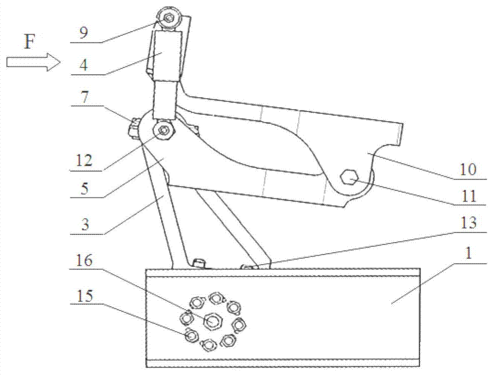
[0053] The front suspension bracket of the heavy-duty truck cab of the present invention is designed to ensure the integrity of the front suspension bracket of the truck when the truck encounters a frontal collision, and prevent the load caused by the fracture of the front suspension bracket The driver's cab falls while absorbing part of the collision energy to effectively protect the occupants in the truck.
[0054] See Image 6 The structure of the front suspension bracket for the heavy truck cab of the present invention is shown in the figure. The front suspension bracket for the heavy truck cab consists of a front suspension right bracket, a front suspension left bracket and a front suspension The bracket balance bar 8 is composed of a front suspension right bracket and a front suspension left bracket installed on the right end and left end of the front suspension bracket balance bar 8 for a fixed connection, wherein: the front suspension right bracket and the front suspension left bracket have the same structure. The front suspension right bracket and the front suspension left bracket are connected to the front suspension left upper bracket 17 and the bottom of the heavy truck cab through the front suspension right upper bracket 10 among them. The front suspension bracket right lower base 2 of the front suspension right bracket is hinged with the front end of the truck right frame 1 through the right No. 4 bolt 16, and the front suspension bracket left lower base of the front suspension left bracket is hinged with the truck The front end of the left frame is hinged with the left No. 4 bolt.
[0055] Referring to Figure 1, when a heavy-duty truck has a frontal collision, the heavy-duty truck cab is subjected to a collision force along the longitudinal direction of the vehicle body, and the truck cab will drive the front suspension right upper bracket 10 and The upper left bracket 17 of the front suspension moves along the longitudinal direction of the car body together. Since the lower right base 2 of the front suspension bracket and the right frame 1 of the truck are hingedly connected by the right 4 bolts 16, the front suspension in the left bracket The lower left base of the bracket and the left frame of the truck are hingedly connected by the left No. 4 bolt. Therefore, the front suspension bracket of the truck cab will rotate around the axis of the right No. 4 bolt 16 and the left No. 4 bolt. During the process, the lower right base 2 of the front suspension bracket and the lower left base of the front suspension bracket will push the right No. 3 bolt 15 and the left No. 3 bolt on the wedge-shaped connection between the right frame 1 of the truck and the left frame of the truck. Movement in the hole, due to the structural characteristics of the wedge structure, that is, when moving from the large end to the small end of the wedge-shaped through hole, a certain amount of friction will be overcome. Therefore, the front suspension bracket of the heavy truck cab is around the right No. 4 bolt 16 and the left During the rotation of the axis of the No. 4 bolt, a certain amount of collision energy will be consumed due to the friction of the wedge-shaped through hole.
[0056] The front suspension right bracket includes front suspension bracket right lower base 2, front suspension bracket right lower bracket 3, front suspension bracket right shock absorber 4, front suspension bracket right middle bracket 5, right No. 5. Bolt 6, front suspension bracket right balance bar cover 7, front suspension bracket right stepped connector 9, front suspension bracket right upper bracket 10, right No. 1 bolt 11, front suspension bracket right stepped bolt 12, right 2 No. bolt 13, right No. 3 nut 14, right No. 3 bolt 15, right No. 4 bolt 16, right No. 4 nut 18, right No. 2 nut 19, right stepped connecting piece nut 20, right rear cylindrical connecting piece 21, Right No. 1 nut 22, right front cylindrical connecting piece 23, right stepped bolt outer nut 24 and right stepped bolt inner nut 25.
[0057] See Image 6 The front suspension bracket balance bar 8 is made of carbon structural steel, which is a cylindrical rod-like structure. The center of both ends of the front suspension bracket balance bar 8 is provided with threaded (blind) holes along the axial direction. The left end surface of the front suspension bracket balance bar 8 is in contact with the right end surface of the front suspension bracket left middle bracket front right wing through hole, while the front suspension bracket balance bar 8 right end surface is in contact with the front suspension bracket right middle bracket 5 front left wing through hole When the left end surface is in contact, the front end of the right middle bracket 5 of the front suspension bracket is connected by the left long shaft of the right stepped bolt 12 of the front suspension bracket and the internal thread of the right end round hole of the front suspension bracket balance rod 8. The front end of the left middle bracket of the front suspension bracket is connected through the right long shaft of the left stepped bolt of the front suspension bracket and the internal thread of the round hole at the left end of the balance rod 8 of the front suspension bracket.
[0058] See Figure 7 The right shock absorber 4 of the front suspension bracket is shaped as a stepped shaft-like rod-like structure, and its upper and lower ends are respectively provided with a through hole for connection, and the upper end of the right shock absorber 4 of the front suspension bracket is open The hole realizes the connection between the upper right bracket 10 of the front suspension bracket and the right shock absorber 4 of the front suspension bracket, and the through hole at the lower end of the right shock absorber 4 of the front suspension bracket realizes the front suspension bracket right middle bracket 5 and the front suspension bracket Right shock absorber 4 connection, front suspension bracket right shock absorber 4 is divided into upper and lower parts, the upper part is a cylinder with a larger diameter, and the lower part of the front suspension bracket right shock absorber 4 is inserted into the cylinder. Diameter cylinder, the small diameter cylinder of the front suspension bracket right shock absorber 4 can be along the axial direction of the front suspension bracket right shock absorber 4 in the front suspension bracket right shock absorber 4 large diameter cylinder During the movement, the resistance generated by the damper arranged inside the large-diameter cylinder of the right shock absorber 4 of the front suspension bracket needs to be overcome to realize the shock absorption effect of the shock absorber.
[0059] See Figure 13-a versus Figure 13-b The center of the front end of the right frame 1 of the truck is provided with a right frame No. 4 through hole for installing the right No. 4 bolt 16, and the right frame No. 4 through hole is evenly distributed with the right No. 3 bolt No. 3 wedge-shaped through hole on the right frame with the same structure as 15.
[0060] The center of the front end of the left frame of the truck is provided with a left frame No. 4 through hole for installing the left No. 4 bolt, and the left frame No. 4 through hole is evenly distributed around the left No. 3 bolt with the same structure No. 3 wedge-shaped through hole of the left frame.
[0061] See Figure 14-a to Figure 14-c , The lower right base of the front suspension bracket 2 is a shell-like structural part welded by 2 square and 2 triangular steel plates or processed by casting technology. The square top plate is provided with the lower right of the front suspension bracket. Bolt through hole of bracket 3; the center of the square side plate connected perpendicularly to the top plate is provided with right No. 4 through hole for installing right No. 4 bolt 16 and the surrounding of No. 4 through hole is evenly distributed for installing right No. 3 bolt 15 The right No. 3 through hole with the same structure; the two right-angle sides of the two triangular steel plates are fixedly connected to the two sides of the square top and side plates, and the outer sides of the two triangular steel plates are the same as the two ends of the square top and side plates. surface.
[0062] See Figure 15-a versus Figure 15-b There is a semicircular groove on the upper end of the lower right bracket 3 of the front suspension bracket, and threaded round holes with internal threads are arranged on the front and rear platforms of the semicircular groove. The right No. 5 bolt 6 is connected to the front , The threaded round hole on the rear platform is equipped to realize the fixed connection with the right balance bar cover 7 of the front suspension bracket. The left and right sides of the lower right bracket 3 of the front suspension bracket are provided with triangular "concave" grooves of equal depth ( See Figure 15-b ), in other words, stiffener plates are arranged within the triangular frame, and the distance between the two sides of the stiffener plate and the two sides of the triangular frame is equal. Two ribs are arranged at the bottom end of the stiffener plate perpendicular to the lower right bracket 3 of the front suspension bracket. There are two through-holes for the ribs, two bottom-end through-holes perpendicular to the bottom end are provided on the bottom frame of the two-ribs through-holes, and the center distance of the two bottom-end through-holes is the same as that on the top plate of the lower right base 2 The bolt through holes are equally spaced.
[0063] Referring to Figure 17, the right middle bracket 5 of the front suspension bracket is a shell-like structure. The front and rear ends of the right middle bracket 5 of the front suspension bracket are composed of left and right wings. The left two wings of the rear end are connected into one body, the front end and the right two wings of the rear end of the right middle bracket 5 of the front suspension bracket are connected into one body. The left and right sides of the right middle bracket 5 of the front suspension bracket are symmetrical and equal, and the front suspension bracket The through holes provided on the left and right wings of the right middle bracket 5 realize the connection with the through holes of the rear end of the right upper bracket 10 of the front suspension bracket. The through holes provided on the front left and right wings of the right middle bracket 5 of the front suspension bracket adopt the front suspension. The right stepped bolt 12 of the mounting bracket realizes the connection with the lower end of the right shock absorber 4 of the front suspension bracket.
[0064] Referring to Fig. 18, the upper right bracket 10 of the front suspension bracket is an "L"-shaped structural member. The long side of the upper right bracket 10 of the front suspension bracket is placed horizontally in the working state, and the upper right bracket 10 (front end) of the front suspension bracket A through hole is provided at the upper end of the short side of the front suspension bracket; the connection between the through hole on the short side and the upper end of the front suspension bracket right shock absorber 4 can be realized by using the right stepped connecting piece 9 of the front suspension bracket. The through holes of the coaxial line are provided on the left and right wings of the long side rear end of the upper right bracket 10, and the through hole of the coaxial line can be connected with the through hole of the rear end of the right middle bracket 5 of the front suspension bracket by using the right No. 1 bolt 11 connection.
[0065] Refer to Figure 19 The right stepped bolt 12 of the front suspension bracket is made of carbon structural steel, which is a stepped shaft structure. The right stepped bolt 12 of the front suspension bracket is divided into three parts from left to right according to the shaft diameter. Sections, from left to right, are the first section shaft, the second section shaft, and the third section screw of the right stepped bolt 12 of the front suspension bracket. The first section shaft has the largest diameter, the left end is provided with a thread, and the third section screw diameter The smallest, the third section of the screw is threaded on the surface, and the first section passes through the front end right wing through hole of the front suspension bracket right middle bracket 5 and the center through hole of the right front cylindrical connector 23 and the front suspension bracket right middle bracket 5 The front left wing through hole is threadedly connected with the threaded hole on the right end of the front suspension bracket balance rod 8. The second section shaft and the third section of the front suspension bracket right stepped bolt 12 pass through the right stepped bolt inner nut 25 and the front suspension in turn After the through hole at the lower end of the right shock absorber 4 of the front suspension bracket is fixedly connected with the thread on the third surface of the right stepped bolt 12 of the front suspension bracket and the outer nut 24 of the right stepped bolt, the first suspension bracket right stepped bolt 12 The right end surface of a section of the shaft is in contact with the left surface of the inner nut 25 of the right stepped bolt.
[0066] Refer to Figure 20 The material of the right stepped connecting piece 9 of the front suspension bracket is made of carbon structural steel, which is a stepped shaft structure. The stepped connecting piece 9 of the front suspension bracket varies from left to right according to the diameter of the cylindrical structure. Divided into three sections, from left to right are the first section shaft, the second section shaft, and the third section screw of the right stepped connector 9 of the front suspension bracket. The first section shaft has the largest diameter and the third section has the smallest diameter. , The third section of the screw is threaded on the surface, where the outer surface of the first section of the front suspension bracket right stepped connecting piece 9 is in contact with the inner surface of the front end of the front suspension bracket right upper bracket 10, and the front suspension bracket The annular right end surface of the first section of the right stepped connecting piece 9 is in contact with the annular left end surface of the upper end of the right shock absorber 4 of the front suspension bracket. In addition, the second section of the right stepped connecting piece 9 of the front suspension bracket is outside the shaft. The surface is in contact with the inner surface of the through hole at the upper end of the right shock absorber 4 of the front suspension bracket, and the third section of the screw of the right stepped connector 9 of the front suspension bracket is fixedly connected with the right stepped connector nut 20.
[0067] Refer to Figure 8-a versus Figure 8-b , The right end surface of the square side plate of the lower right base 2 of the front suspension bracket is in contact with the left end surface of the front end of the right frame 1 of the truck, and the right 4 bolt 16 is inserted into the square side plate in the lower right base 2 of the front suspension bracket The right No. 4 through hole in the center and the right frame center through hole surrounded by 8 wedge-shaped through holes at the front end of the truck frame 1 and hingedly connected with the right No. 4 nut 18, and then adopt 8 identical structures The right No. 3 bolt 15 is inserted into the right No. 3 through hole evenly distributed on the square side plate of the front suspension bracket and the right lower base 2 and the wedge-shaped through hole is evenly distributed on the front end of the right frame 1 of the truck, and is fitted with the right No. 3 nut 14 Into a fixed connection.
[0068] Refer to Figure 9-a versus Figure 9-b , The bottom surface of the lower right bracket 3 of the front suspension bracket is in contact with the top surface of the lower right base 2 of the front suspension bracket, and the right No. 2 bolt 13 is inserted into the top plate of the lower right base 2 of the front suspension bracket along the vertical direction. The bolt through hole of the front suspension bracket and the bottom through hole of the lower right bracket 3 of the front suspension bracket are fixedly connected with the right No. 2 nut 19.
[0069] Refer to Figure 10-a versus Figure 10-b , The right end surface of the front end through hole of the front suspension bracket right upper bracket 10 is in contact with the left end surface of the upper end through hole of the front suspension bracket right shock absorber 4, the front suspension bracket right stepped connector 9 is inserted into the front suspension bracket right upper bracket in turn 10 The through hole at the front end and the through hole at the upper end of the right shock absorber 4 of the front suspension bracket are fixedly connected with the right stepped connecting piece nut 20.
[0070] Refer to Figure 11-a versus Figure 11-b , The right rear cylindrical connector 21 is sequentially inserted into the left wing through hole at the rear end of the right middle bracket 5 of the front suspension bracket and the right wing through hole at the rear end of the right middle bracket 5 of the front suspension bracket. The outer cylindrical surface of the right rear cylindrical connector 21 and Front suspension bracket Right middle bracket 5 Rear left wing through hole, right wing through hole inner cylindrical surface is small interference fit, at the same time the left end surface of the right rear cylindrical connector 21 and the front suspension bracket right middle bracket 5 rear left wing The left end face of the through hole is coplanar, and the right end face of the right rear cylindrical connector 21 is coplanar with the right end face of the through hole of the rear right wing of the front suspension bracket right middle bracket 5; the front suspension bracket right upper bracket 10 rear left wing No. 1 The right end surface of the through hole is in contact with the left end surface of the right rear cylindrical connector 21, and the left end surface of the No. 1 through hole in the rear right wing of the right upper bracket 10 of the front suspension bracket is in contact with the right end surface of the right rear cylindrical connector 21; The right No. 1 bolt 11 is inserted into the front suspension bracket, the right upper bracket 10, the rear right wing No. 1 through hole, the right rear cylindrical connecting piece 21, and the front suspension bracket, the right upper bracket 10, the rear left wing No. 1 through hole in turn. It is fixedly connected with the right No. 1 nut 22, and the right No. 1 bolt 11 is in clearance fit with the inner cylindrical surface of the right rear cylindrical connecting piece 21, thereby realizing the front suspension bracket in the front suspension bracket and the right middle bracket 5 The suspension bracket is connected with the hinge of the upper right bracket 10.
[0071] Refer to Figure 12-a versus Figure 12-b , The semicircular hole surface at the top of the right lower bracket 3 of the front suspension bracket is in contact with the outer cylindrical surface of the right front cylindrical connecting piece 23, and the semicircular hole surface of the right balance bar cover 7 of the front suspension bracket is connected to the outer surface of the right front cylindrical connecting piece 23 Cylinder surface contact connection, and the front suspension bracket right balance bar cover 7 is installed with the through hole of the right No. 5 bolt 6 at the front end and the rear end is installed with the bottom end surface of the No. 5 through hole of the right No. 5 bolt 6 and the front suspension bracket lower right bracket The top surface of 3 is contacted and connected, and 2 right No. 5 bolts of the same structure are inserted into the front and rear No. 5 through holes on the right balance bar cover of the front suspension bracket and the front and rear threads of the upper end of the lower right bracket 3 of the front suspension bracket The inside of the hole is threaded connection; the right end surface of the front end left wing through hole of the front right middle bracket 5 of the front suspension bracket is in contact with the left end surface of the right front cylindrical connector 23, and the left end surface of the front end right wing through hole of the front right middle bracket 5 of the front suspension bracket is connected to the right front tube The right end surface of the front suspension bracket 23 is in contact and connection; the right end surface of the front suspension bracket balance bar 8 is in contact with the left surface of the front left wing through hole of the front suspension bracket right middle bracket 5; the left long axis of the front suspension bracket right stepped bolt 12 Partially inserted into the front end right wing through hole of the front suspension bracket right middle bracket 5, the center through hole on the right front cylindrical connector 23 and the front suspension bracket right middle bracket 5 front left wing through hole, and the right end of the front suspension bracket balance bar 8 The central hole is threaded and fixed; the right short shaft of the right stepped bolt 12 of the front suspension bracket is inserted into the right stepped bolt inner nut 25 and the front suspension bracket right shock absorber 4 lower end through the hole and the right stepped bolt outer nut 24 screw fixed.
[0072] The front suspension left bracket includes a front suspension bracket left lower base, front suspension bracket left lower bracket, front suspension bracket left shock absorber, front suspension bracket left middle bracket, left No. 5 bolt, front suspension bracket Left balance bar cover, front suspension bracket left stepped connector, left No. 1 bolt, front suspension bracket left stepped bolt, left No. 2 bolt, left No. 3 bolt, left No. 4 bolt, front suspension bracket, left upper bracket 17. Left No. 4 nut, left No. 2 nut, left stepped connecting piece nut, left rear cylindrical connecting piece, left No. 1 nut, left front cylindrical connecting piece, left stepped bolt outer nut and left stepped bolt inner nut .
[0073] The rear end of the upper left bracket of the front suspension bracket is equipped with the rear end of the left middle bracket of the front suspension bracket and fixedly connected with the left No. 1 bolt, and the left No. 1 bolt between the two holes of the left middle bracket of the front suspension bracket The kit has a left rear cylindrical connector, the front end of the left upper bracket of the front suspension bracket is hinged with the upper end of the left shock absorber of the front suspension bracket using the left stepped connector of the front suspension bracket, and the lower end of the left shock absorber of the front suspension bracket It is hinged with the right short axis of the left stepped bolt of the front suspension bracket, and the left long axis of the left stepped bolt of the front suspension bracket is inserted into the front end of the left middle bracket of the front suspension bracket and the front suspension bracket balance bar (8 ) Threaded connection at the other end of the front suspension bracket, the left side of the front suspension bracket left stepped bolt between the two holes at the front end of the front suspension bracket is fitted with a left front cylindrical connector, using the front suspension bracket left balance bar cover The left front cylindrical connector is fixed to the upper end of the lower left bracket of the front suspension bracket, and the lower end of the lower left bracket of the front suspension bracket is fixed on the left lower base of the front suspension bracket with the left No. 2 bolt. The front suspension right bracket and the front suspension left bracket are fixedly connected to the front suspension left upper bracket 17 and the bottom of the heavy truck cab through the front suspension right upper bracket 10, and the front suspension bracket right in the front suspension right bracket The lower base 2 and the front end of the right frame 1 of the truck are hinged with the right No. 4 bolt 16 and (in the embodiment) are fixedly connected by 8 right No. 3 bolts 15 with the same structure. The front suspension is the front suspension in the left bracket. The lower left base of the bracket and the front end of the left frame of the truck are hinged with the left No. 4 bolts, and (in the embodiment) are fixedly connected with 8 left No. 3 bolts with the same structure.
[0074] The front suspension left bracket has the same structure as the front suspension right bracket, that is, the lower left base of the front suspension bracket has the same structure as the lower right base 2 of the front suspension bracket, and the lower left bracket of the front suspension bracket has the same structure as the lower right bracket 3 of the front suspension bracket. , The left shock absorber of the front suspension bracket has the same structure as the right shock absorber 4 of the front suspension bracket, the left middle bracket of the front suspension bracket has the same structure as the right middle bracket 5 of the front suspension bracket, the left No. 5 bolt and the right No. 5 bolt 6 The structure is the same, the front suspension bracket left balance bar cover and the front suspension bracket right balance bar cover 7 have the same structure, the left stepped connecting piece of the front suspension bracket and the right stepped connecting piece of the front suspension bracket 9 have the same structure, the front suspension The upper left bracket 17 of the mounting bracket has the same structure as the upper right bracket 10 of the front suspension bracket, the left No. 1 bolt has the same structure as the right No. 1 bolt 11, and the left stepped bolt of the front suspension bracket has the same structure as the right stepped bolt 12 of the front suspension bracket. The left No. 2 bolt has the same structure as the right No. 2 bolt 13, the right No. 3 nut 14 and the left No. 3 nut, the left No. 3 bolt and the right No. 3 bolt 15 have the same structure, and the left No. 4 bolt has the same structure as the right No. 4 bolt 16. The left No. 4 nut has the same structure as the right No. 4 nut 18, the left No. 2 nut and the right No. 2 nut 19 have the same structure, the left stepped connecting piece nut has the same structure as the right stepped connecting piece nut 20, and the left rear cylindrical connecting piece has the same structure The right rear cylindrical connector 21 has the same structure, the left No. 1 nut has the same structure as the right No. 1 nut 22, the left front cylindrical connector has the same structure as the right front cylindrical connector 23, and the left stepped bolt outer nut is the same as the right stepped bolt outer nut. The nut 24 has the same structure, and the left stepped bolt inner nut has the same structure as the right stepped bolt inner nut 25.

PUM

no PUM

Description & Claims & Application Information

We can also present the details of the Description, Claims and Application information to help users get a comprehensive understanding of the technical details of the patent, such as background art, summary of invention, brief description of drawings, description of embodiments, and other original content. On the other hand, users can also determine the specific scope of protection of the technology through the list of claims; as well as understand the changes in the life cycle of the technology with the presentation of the patent timeline. Login to view more.

Similar technology patents

PET-CT examining bed

PendingCN112716512Aavoid radiation damagefall prevention
Owner:SHANXI MEDICAL UNIV

Body structure and vehicle

ActiveCN109204546AProtect occupantsreduce distortion
Owner:BYD CO LTD

Intelligent nursing system

InactiveCN106333557Afall prevention
Owner:刘哲

Classification and recommendation of technical efficacy words

  • Strong energy absorption capacity
  • fall prevention

Intelligent nursing system

InactiveCN106333557Afall prevention
Owner:刘哲

PET-CT examining bed

PendingCN112716512Aavoid radiation damagefall prevention
Owner:SHANXI MEDICAL UNIV
Why Eureka
Try Eureka