Ship line with stern transom plate and unbalanced rudder blade designing method

A design method and unbalanced technology, applied in the design of hull and rudder blade, including stern cover plate hull and unbalanced rudder blade design, single rudder ship and multi-rudder ship field, which can solve the problem of reduced rudder efficiency and scissors difference. Large and other problems, to achieve the effect of improving rudder efficiency, improving maneuverability and saving energy

Inactive Publication Date: 2015-06-10
JIANGSU UNIV OF SCI & TECH
View PDF4 Cites 0 Cited by
  • Summary
  • Abstract
  • Description
  • Claims
  • Application Information

AI Technical Summary

Problems solved by technology

However, this favorable factor can only be better reflected when the hull where the rudder blades are installed is flat. The leaf is a mechanism that can rotate around the center of the rudder stock, so the existing technology can only make the upper edge of the rudder and the bottom plate of the hull have a good coincidence state (that is, the gap is the smallest) at a certain corner of the rudder blade, so that the The rudder blade has a better rudder effect at this turning angle
For example, for a single-stern and single-rudder ship, at a rudder angle of 0°, the shape of the upper edge of the rudder blade can be parallel to the shape of the stern bottom plate and the gap can be minimized, so that the rudder effect is the best at this time, but when the rudder turns At a certain angle, in order to prevent the rudder blade from colliding with the hull or due to the shape of the hull itself, the parallel and close relationship between the shape of the upper edge of the rudder blade and the shape of the bottom plate of the hull must be lost. At this time, the gap becomes a scissors difference. reducing the rudder efficiency

Method used


Image

  • Ship line with stern transom plate and unbalanced rudder blade designing method
  • Ship line with stern transom plate and unbalanced rudder blade designing method
  • Ship line with stern transom plate and unbalanced rudder blade designing method

Examples


Embodiment Construction

[0014] The present invention will be further described below in conjunction with the accompanying drawings and specific embodiments.

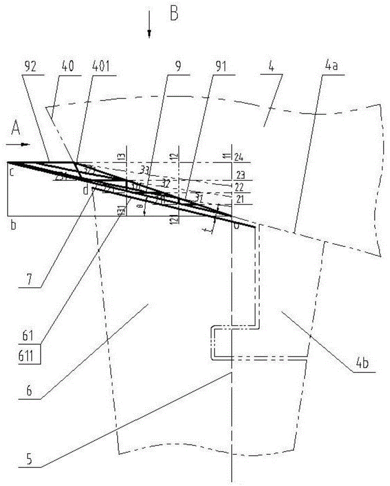
[0015] figure 1 It is a side view (straight sectional view) of the present invention, showing the relative position of the rudder and the hull when part of the straight section line and the rudder are at a rudder angle of 0°;

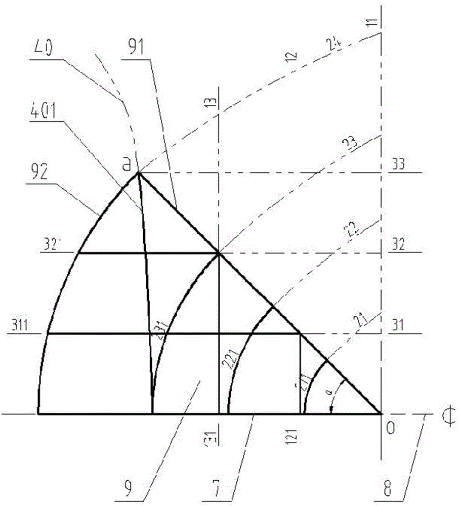
[0016] figure 2 It is the A-direction view (station plan) of the present invention, due to symmetry, only part of the molded line on the port side is shown;

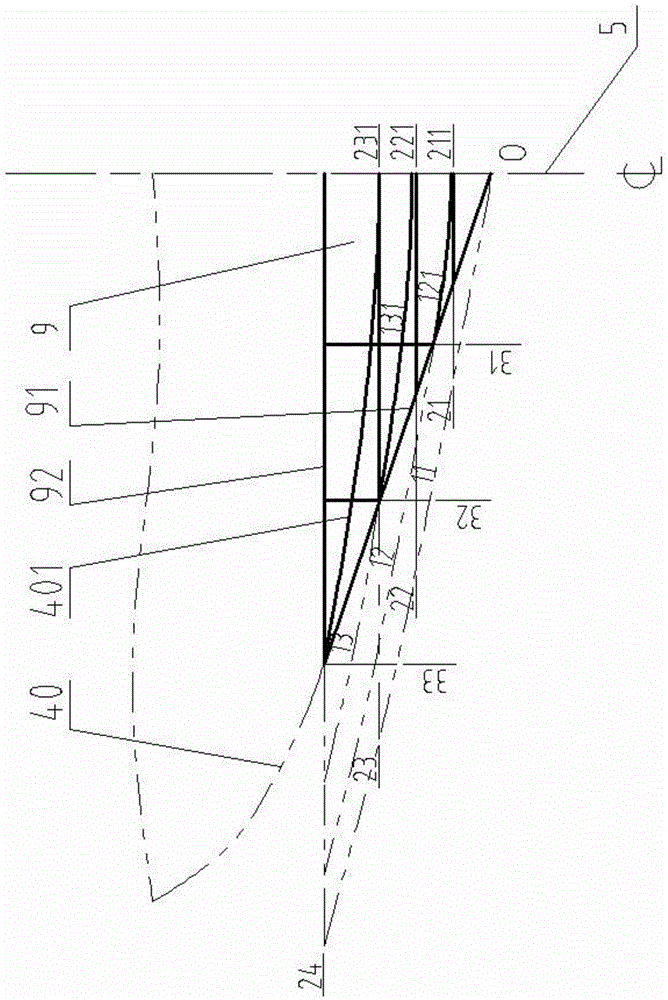
[0017] image 3 It is a B-direction view (waterline view) of the present invention. Due to symmetry, only part of the molded line on the port side is shown.

[0018] like figure 1 , figure 2 , image 3 , point o is the intersection of the centerline 5 of the rudder stock and the 0° straight profile line 4a of the hull.

[0019] The design method of hull shape line with stern plate and unbalanced rudder rudder blade is as follows:

[0020] 1. in image 3 ...


PUM


Abstract

The invention discloses a ship line with a stern transom plate and an unbalanced rudder blade designing method; the ship bottom shape at the mounting position of a ship body rudder blade is a conical ship body cyclogenesis plane; within a rotation angle range of the rudder blade, for a streamline rudder blade, the upper end surface of the rudder blade is a curved plane parallel to the ship body cyclogenesis curved plane; and for a flat-plate rudder blade, the upper end line of the rudder blade is a curved line parallel to the ship body cyclogenesis curved plane. According to the invention, coordination of characteristics, such as the ship line, a rudder blade line, a lower rudder bearing structure and the like, are sufficiently taken into consideration; and the ship line disclosed by the invention is used for various single-rudder ships or multi-rudder ships with the stern transom plates and semi-balanced or unbalanced rudders. According to the invention, within all rotation angle ranges of the rudder blade, the shape of the upper edge of the rudder blade and the shape of a ship bottom plate are always kept parallel, so that the clearance can be minimized and an optimal space is always kept; therefore, the rudder effect is effectively enhanced and can be enhanced by more than one time, so that the operability of the ship is improved and energy is saved.

Description

technical field [0001] The invention relates to a design method of a hull and rudder blades, in particular to a design method of a hull with a stern seal plate and an unbalanced rudder blade, which is suitable for single-rudder ships and multi-rudder ships with a stern seal plate and semi-balanced or unbalanced rudders. A rudder ship belongs to the technical field of ships. Background technique [0002] The maneuverability of the ship plays an important role in the overall performance of the ship and the quality of the ship's navigation performance, and the rudder plays a decisive role in the maneuverability of the ship. Therefore, how to improve the rudder efficiency has become one of the important issues studied by shipbuilders. It has long been recognized theoretically that the aspect ratio plays a decisive role in the rudder effect under the condition that the rudder area and rudder section remain unchanged. . However, due to the limitation of the ship's draft and wate...

Claims


Application Information

Patent Timeline
Patent Type & Authority Patents(China)
IPC IPC(8): B63B9/00B63H25/38
Inventor 周玉龙宗钰炀王志东
Owner JIANGSU UNIV OF SCI & TECH
Why Eureka
Try Eureka