
Self-loading operation mechanism of loading machine

An operating mechanism and self-loading and unloading technology, applied in the direction of lifting devices, etc., can solve the problems of inconvenient operation and poor stability, and achieve the effects of convenient operation, improved work efficiency and stable operation

Inactive Publication Date: 2013-02-13
ORDNANCE TECH RES INST OF THE GENERAL ARMAMENT DEPT PLA
View PDF6 Cites 6 Cited by
  • Summary
  • Abstract
  • Description
  • Claims
  • Application Information

AI Technical Summary

Problems solved by technology

[0003] The purpose of the present invention is to provide a loader self-loading and unloading operation mechanism to solve the problems of poor stability and inconvenient operation of the loader, and to expand the application range of the loader

Method used


Image

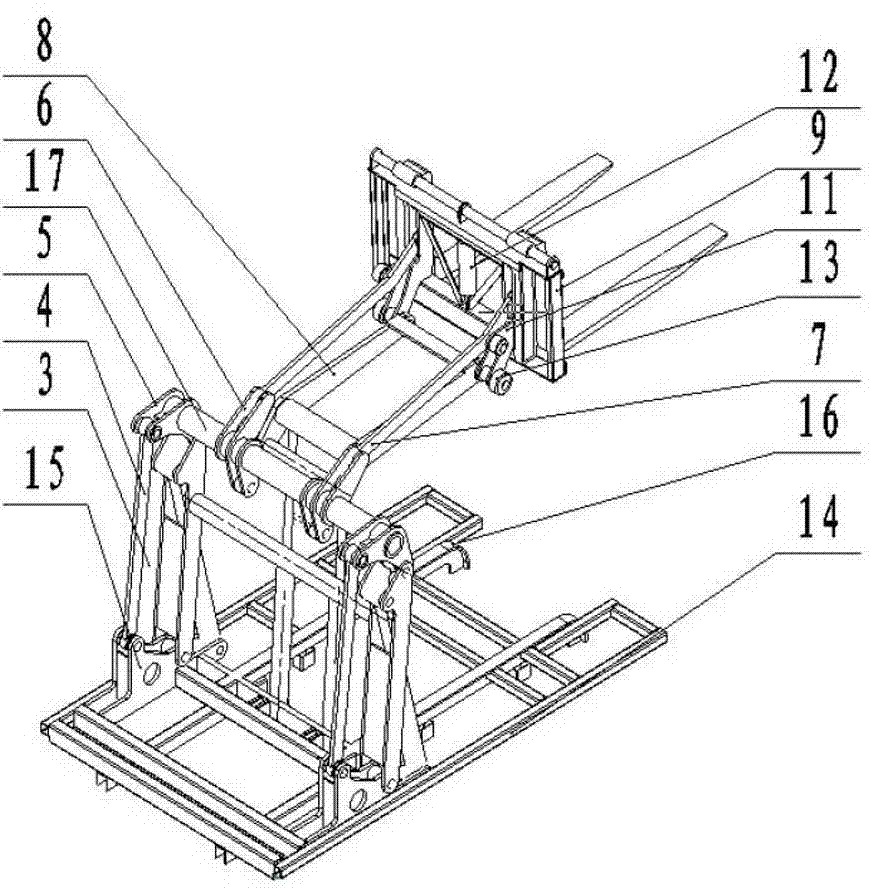
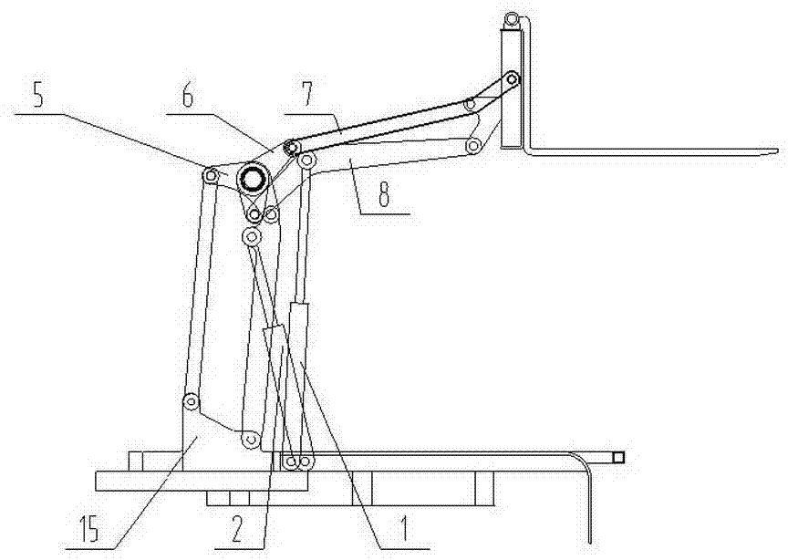
  • Self-loading operation mechanism of loading machine
  • Self-loading operation mechanism of loading machine
  • Self-loading operation mechanism of loading machine

Examples


Embodiment Construction

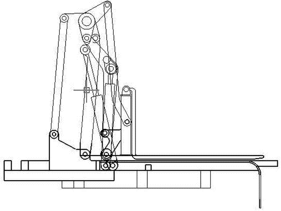
[0017] The invention comprises four components of an upper parallel four-bar mechanism, a lower parallel four-bar mechanism, a cargo fork mechanism and a vehicle frame.

[0018] Such as figure 1 , figure 2 As shown, the lower parallel four-bar mechanism includes two bases 15, two main arms 3, two main arm hydraulic cylinders 2, two lower rods 4, two outer torsion arms 5 and a connecting shaft 17 and other parts . Two bases 15 are respectively fixed on both sides of the vehicle frame 14, and a main arm 3, a pull down rod 4 and a main arm hydraulic cylinder 2 are respectively hinged on each base 15. An outer torsion arm 5 is respectively socketed and fixed at the two ends of the connecting shaft 17, one end of the outer torsion arm 5 is hinged with the upper end of the main arm 3 on the side, and the other end of the outer torsion arm 5 is connected to the pull-down rod 4 on the side. The upper end is hinged. The piston rod on each main arm hydraulic cylinder 2 is hinged on...


PUM


Abstract

The invention relates to a self-loading operation mechanism of a loading machine. The structure of the operation mechanism comprises a fork mechanism which is used for bearing, loading and unloading cargoes, an upper parallel four-rod mechanism which is connected to the fork mechanism through a shaft and is used for controlling the fork mechanism to stretch and lift, a lower parallel four-rod mechanism which is connected to the upper parallel four-rod mechanism through a shaft and is used for controlling the whole operation mechanism to rise and fall and a frame which is hinged with the lower parallel four-rod mechanism and serves as a bearing body of the operation mechanism. Rollers are arranged on the fork mechanism, and sliding rails which are used for bearing the rollers are fixed on the frame. The operation mechanism is flexible in action, convenient to operate, stable in operation, wide in operation application range, suitable to various harsh working terrains and capable of implementing moving operation in a narrow working field and improving the stability of loading operation and convenience of operation.

Description

technical field [0001] The invention relates to a structural component of a loader, in particular to a loader self-loading and unloading operation mechanism. Background technique [0002] In the process of material handling, a variety of handling equipment such as forklifts, flatbed trucks, tractors, and pallet trucks are usually used. The work efficiency is very low, and there are certain safety hazards. In addition, short-distance material loading and unloading is carried out in various harsh environments such as mountains, ravines, jungles, deserts, tidal flats, and snowy areas. It is difficult for large forklifts and transport vehicles to reach the handling site, and it is also difficult to carry out in small workplace corresponding handling work. During the loading and unloading process of traditional crawler trucks, there are problems of poor stability and inconvenient operation. Contents of the invention [0003] The purpose of the present invention is to provide ...

Claims


Application Information

Patent Timeline
IPC IPC(8): B66F9/20B66F9/22
Inventor 穆希辉杜峰坡卞学良罗磊马振书葛强陈安成郭浩亮吕凯
Owner ORDNANCE TECH RES INST OF THE GENERAL ARMAMENT DEPT PLA
Learn More