Original-position denitrification reactor in flowing water area

A reactor, denitrification technology, applied in chemical instruments and methods, water/sewage multi-stage treatment, water/sludge/sewage treatment, etc., can solve the problems of secondary pollution, short life, weak denitrification ability, etc. Achieve the effect of low maintenance cost, long service life and low cost

Active Publication Date: 2014-01-29
ZHEJIANG UNIV
View PDF5 Cites 0 Cited by
  • Summary
  • Abstract
  • Description
  • Claims
  • Application Information

AI Technical Summary

Problems solved by technology

However, these existing technical means still have one or more deficiencies such as weak denitrification ability, high application and operating costs, short life, extra space, low applicability, and risk of secondary pollution, which further limit The application and promotion of these technical means can overcome the above shortcomings at the same time, and realize the continuous, automatic, efficient, in-situ denitrification technology in flowing waters has not been reported, which will affect the effectiveness of water eutrophication control.

Method used


Image

  • Original-position denitrification reactor in flowing water area

Examples


Embodiment Construction

[0008] Further illustrate the present invention below in conjunction with accompanying drawing

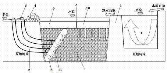
[0009] refer to figure 1 The in-situ denitrification reactor for flowing waters of the present invention comprises a grit chamber 1, a drop dam 2, a reaction tank 3 and a water retaining wall 4 piled up with pebbles which are successively arranged on the river bed along the flow direction, and the lower layer of the reaction tank 3 is filled with Sawdust layer 7. A PVC pipe 8 for collecting denitrification tail water is laid at the bottom of the wood chip layer 7 near the cobblestone water retaining wall 4. The PVC pipe 8 has a plurality of tail water collection holes 11 with gauze, and the PVC pipe 8 The water outlet is connected to the soft underground drainage pipe 5, which passes through the bottom of the river bed below the cobblestone water retaining wall 4, and its water outlet is exposed on the surface of the river bed downstream of the cobblestone water retaining wall 4. ...


PUM


Abstract

The invention discloses an original-position denitrification reactor in a flowing water area. The original-position denitrification reactor in the flowing water area comprises a grit chamber, a hydraulic drop dam, a reaction tank and a retention wall, wherein the retention wall is formed by cobblestones in stacked mode, and the grit chamber, the hydraulic drop dam, the reaction tank and the retention wall are arranged in sequence along the water flowing direction. The lower layer of the reaction tank is filled with a saw dust layer, a polyvinyl chloride (PVC) pipe used to collect denitrification tail water is laid at the bottom of the saw dust layer and is close to the cobblestoned retention wall, water outlets of the PVC pipe are connected with flexible drainage underground pipes, the flexible drainage underground pipes penetrate through the bottom of a riverbed under the cobblestoned retention wall and are exposed on the surface of the downstream riverbed behind the cobblestoned retention wall, and drainage faucets are mounted on water outlets of the flexible drainage underground pipes. A sticky sand layer and a gravel layer are laid side by side on the saw dust layer, wherein the sticky sand layer is close to the retention wall, and the gravel layer is close to the hydraulic drop dam. The denitrification reactor is made of local materials, and is simple to construct and low in cost; the fall changes of the flowing water area from top to bottom can be used to carry out sand settling and hydraulic drop oxygenation treatment, and continuous treatment and purification of a polluted water area can be achieved; and high-concentration nitrogen in streams which flow into lakes or reservoirs, drainage channels, city watercourses and other flowing water areas can be effectively removed.

Description

technical field [0001] The invention relates to an in-situ denitrification reactor for flowing water areas. Background technique [0002] With the increase of human industrial and agricultural production intensity and the increase of demand for water resources, the eutrophication of lakes, reservoirs, estuaries, coasts and other water bodies caused by excess nutrients such as nitrogen and phosphorus has become an urgent issue in the process of social and economic development and ecological environment construction. One of the key issues that needs to be addressed. Flowing waters such as streams, ditches, and river courses are not only the main channel for transporting nutrients such as nitrogen and phosphorus from the upper land area to the lower water area, but also play an important role in regulating the regional and global nitrogen cycle, and are also important sources of life, production, and entertainment in many areas. The direct or indirect source of water is closel...

Claims


Application Information

Patent Timeline
Patent Type & Authority Patents(China)
IPC IPC(8): C02F9/14
Inventor 陈丁江张柏发黄宏
Owner ZHEJIANG UNIV
Why Eureka
Try Eureka