

Piston rod separation device of piston-diaphragm pump as well as piston-diaphragm pump
A separation device and piston rod technology, which is applied to the components of the pumping device for elastic fluid, the pump, the pump element, etc., can solve the problems such as the small size of the piston cylinder liner, the separation of large-scale maintenance tools, and the difficult separation of the combination, etc. To achieve the effect of simple structure, low use cost, easy maintenance and repair
- Summary
- Abstract
- Description
- Claims
- Application Information
AI Technical Summary
Problems solved by technology
Method used
Image

Examples
Embodiment Construction
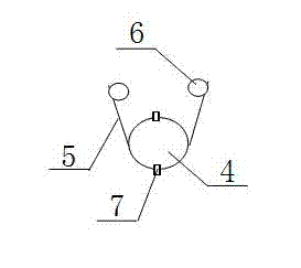
[0027] Combine below figure 2 and image 3 , the present invention is further described:
[0028] Such as figure 2 As shown, a piston diaphragm pump piston rod separation device for pumping iron concentrate slurry includes a hoop 4, a pull rod 5, a fixed ring 6, and a movable buckle 7. The hoop 4 is spliced by two semicircular metal rings through the movable buckle 7, and the circumference of the hoop 4 can be adjusted within a certain range by adjusting the movable buckle 7. The adjustable design of the 4 circumferences of the hoop makes the separation device of the present invention have the advantages of convenient operation and suitable for piston rods of different diameters.
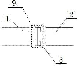
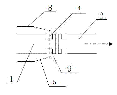
[0029] The hoop 4 is sleeved in the annular groove 9 of the piston rod 1, and the two ends of the hoop 4 are respectively connected to a fixing ring 6 through a tie rod 5, and the two fixing rings 6 are respectively sleeved on two different screw rods 8 and are The nut on the screw rod 8 can...
PUM
 Abstract
Description
Claims
Application Information