
High-power LED lamp

A LED lighting, high-power technology, applied in cooling/heating devices of lighting devices, lighting and heating equipment, semiconductor devices of light-emitting elements, etc., can solve the problems of light loss, low light efficiency, high heat generation, etc., and achieve lighting brightness Improve, reduce usage, improve cooling efficiency

Active Publication Date: 2013-11-20
南京永乐照明灯饰有限公司
View PDF13 Cites 0 Cited by
  • Summary
  • Abstract
  • Description
  • Claims
  • Application Information

AI Technical Summary

Problems solved by technology

[0014] (2) In existing LED lamps, each LED chip will reflect and block each other, which will easily cause light loss, resulting in low light efficiency and high heat generation

Method used


Image

  • High-power LED lamp
  • High-power LED lamp
  • High-power LED lamp

Examples


Embodiment Construction

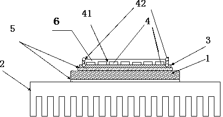
[0055] Combine below Figure 2 to Figure 14 , the present invention is further described:

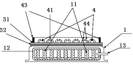
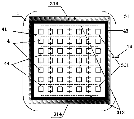
[0056] Such as figure 2 As shown, the "chip on board" in high-power LED lamps means that the chip is directly packaged on the uniform temperature board, and its specific structure is as follows:

[0057] Attach the capillary tissue 12 to the inner wall of the vapor chamber 1, seal the vapor chamber of the support, 11, and leave an injection port 13, and coat a layer of high thermal conductivity insulating medium on the upper surface of the vapor chamber 1 to form An insulating dielectric layer 32.

[0058] Then a circuit layer 31 is made on the insulating medium layer 32, and the first stage of the process is completed through the processes of die bonding, gold wire bonding, reflector support 43, and phosphor powder 41 (needed only for white light source).

[0059] To complete the structure of the above process, add working fluid to the injection port 13 and vacuumize, and then seal...


PUM


Abstract

The invention relates to a high-power LED lamp, which includes an LED lighting unit, a temperature-uniforming plate and a radiating structure, wherein the LED lighting unit is fixed above the temperature-uniforming plate; the radiating structure is fixed under the temperature-uniforming plate; a graphite patch is arranged between the radiating structure and the temperature-uniforming plate for heat transfer; a support body inside the temperature-uniforming plate comprises a plurality of honeycomb one-sided thin sheets; each honeycomb one-sided thin sheet includes a plurality of grooves and a plurality of connecting parts; a connecting part is arranged between any two grooves for transition, and any two honeycomb one-sided thin sheets are fixedly connected through the connecting parts to form a honeycomb hole or any two honeycomb one-sided thin sheets are fixedly connected through the bottom parts of the grooves to form a honeycomb hole; and a plurality of liquid flowing holes are formed in each honeycomb one-sided thin sheet, so that one liquid flowing hole is formed between the adjacent two honeycomb holes. The graphite patch with excellent thermal conduction is arranged between the radiating structure and the temperature-uniforming plate, compared with the traditional structure, the high-power LED lamp reduces one layer of heat conducting silica gel, and greatly improves the radiating efficiency.

Description

technical field [0001] The invention relates to an LED lamp, in particular to a high-power LED lamp. Background technique [0002] With the continuous improvement of the luminous efficiency of LED light-emitting chips, it is just around the corner that LED lighting will replace traditional lighting. In addition to the luminous efficiency of the LED chip itself, the luminous efficiency of the lamp is also critical to the packaging process and the design of the optics, mechanism, drive power, and heat dissipation of the lamp. [0003] The optical design lies in the design of the light distribution of the light source of the lamp according to the needs of the user. In addition, the light transmission and reflection design of the lens and reflector is related to the light effect of the lamp. The conversion efficiency of the driving power is high, which means that the power consumption is low, and the light efficiency will naturally be improved. A good heat dissipation design c...

Claims


Application Information

Patent Timeline
Patent Type & Authority Patents(China)
IPC IPC(8): F21S2/00F21V29/00F21V17/00F21V31/00F21Y101/02F21K9/235F21V29/56F21V29/76F21V29/83F21Y115/10
Inventor 殷逢宝
Owner 南京永乐照明灯饰有限公司
Learn More