
Rapid hot melt type optical fiber connector

A connector, hot-melt technology, applied in the coupling of optical waveguides, etc., can solve the problems of communication interruption, low success rate, and inability to reuse, and achieve the effect of solving the low success rate.

Active Publication Date: 2013-02-13
NANJING PUTIAN TELEGE INTELLIGENT BUILDING
View PDF5 Cites 14 Cited by
  • Summary
  • Abstract
  • Description
  • Claims
  • Application Information

AI Technical Summary

Problems solved by technology

[0005] Advantages of the present invention: 1) Compared with the previous structure, when the connector is inserted into the adapter, the present invention solves the problem of the retraction of the pin by using the redundant section of optical fiber, and the optical cable and the connector shell are clamped tightly, so that when the optical cable at the end of the connector is subjected to When the force is applied, it will not drive the front ferrule to move together, thus solving the problem of communication interruption caused by the force of the tail optical cable in the traditional connector during use; 3) The connector in the present invention uses a surplus section in front, so that the front end of the connector becomes a whole, avoiding the problem of assembling too many parts during the construction process; 4) The present invention Through ingenious structural design, when the first fusion splicing fails, the secondary fusion splicing of optical fibers can be completed through structural adjustment, which solves the problem that the success rate of most hot-melt optical fiber connectors is low and cannot be reused; 5) The invention is applicable to SC, LC, FC and other types of hot-melt optical fiber quick connectors with coated optical fiber, 0.9 optical cable, 2.0 round optical cable, 3.0 round optical cable, and butterfly optical cable

Method used


Image

  • Rapid hot melt type optical fiber connector
  • Rapid hot melt type optical fiber connector
  • Rapid hot melt type optical fiber connector

Examples


Embodiment

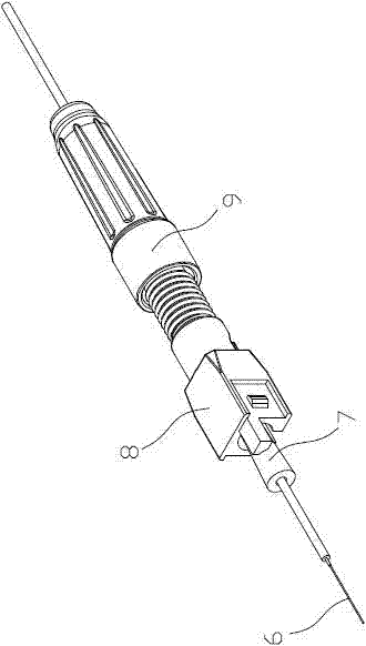
[0026] When assembling the hot-melt optical fiber connector on site, first thread the tightening nut 9, the tail shell 8, and the heat-shrinkable sleeve 7 into the optical fiber 6 at the cable end in sequence, and cut to length with a special tool. figure 2 .

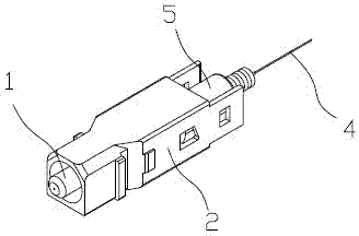
[0027] Put the prefabricated optical fiber 4 together with the connector housing 2 and the ferrule assembly 1 into a special tool for cutting to length, as shown in the attached image 3 .

[0028] Use a fiber optic fusion splicer to perform fiber fusion, and fuse the fiber 6 at the cable end and the prefabricated fiber 4 into a whole, as shown in the attached Figure 4 .

[0029] Put the heat-shrinkable sleeve 7 into the optical fiber fusion joint, and wrap one end on the outside of the inner tapered structure 5-1 of the connection bushing, and heat shrink it with a heat-shrinkable tube heating device to protect it outside the optical fiber fusion joint. Figure 5 .

[0030] Insert the tail shell 8 into the positi...


PUM


Abstract

The invention relates to a rapid hot melt type optical fiber connector which is characterized by comprising a core inserting component, a connector shell, a prefabricated optical fiber, a connecting lining, a cable end optical fiber, a thermal shrinkage protecting tube, a tail part shell and a tightening screw cap. The connector has the following advantages: 1), as the problem of thrusting needle return is solved by utilizing a surplus optical fiber section, and an optical fiber cable is tightly clamped with a connector shell, a front end inserting core is not driven to move together when the tail optical fiber cable of the connector is stressed, so that the problem that the communication is interrupted as the tail part optical fiber cable of a conventional connector is stressed when being used is solved; 2), the problem that too many components are assembled in the construction process is solved; 3), the problem that most conventional hot melt type optical fiber connectors are low in success rate and cannot be used repeatedly is solved; and 4), the rapid hot melt type optical fiber connector is applicable to various rapid hot melt type optical fiber connectors such as an SC (straight connector), an LC (lucent connector) and an FC (fixed connector) with coating layer optical fibers, 0.9 optical fiber cables, 2.0 circular optical fiber cables, 3.0 circular optical fiber cables and butterfly optical fiber cables.

Description

technical field [0001] The invention relates to a hot-melt optical fiber quick connector, which belongs to the technical field of optical fiber connection devices. Background technique [0002] At present, there are usually two structures of heat-melt optical fiber quick connectors. One is to fuse the optical fiber at the cable end with the prefabricated optical fiber, and then fix the optical fiber at the cable end, the prefabricated optical fiber and the ferrule as a whole through a heat shrinkable tube. When inserting the fiber optic adapter, the optical fiber at the cable end moves with the ferrule. The other is to give a small amount of excess fiber at the rear end of the heat shrinkable tube at the tail of the connector, so that the excess fiber bends when the ferrule is inserted into the adapter. One kind of movement mode: when the optical cable at the end of the connector is stressed, it will drive the optical fiber at the cable end and the ferrule to move together. ...

Claims


Application Information

Patent Timeline
IPC IPC(8): G02B6/255G02B6/38
Inventor 李志宏管陈明关梦琳张绪
Owner NANJING PUTIAN TELEGE INTELLIGENT BUILDING
Learn More