Eureka AIR delivers breakthrough ideas for toughest innovation challenges, trusted by R&D personnel around the world.

Electromagnetic touch device

A touch device, electromagnetic touch technology, applied in the direction of electrical digital data processing, instruments, data processing input/output process, etc., can solve the problem of susceptibility to interference, active electromagnetic stylus replacement, difficult signal-to-noise ratio, etc. problem, to achieve the effect of a wide range of applications

Active Publication Date: 2013-02-13
贺爱兰 +3
View PDF6 Cites 11 Cited by
  • Summary
  • Abstract
  • Description
  • Claims
  • Application Information

AI Technical Summary

Problems solved by technology

[0005] In actual use, it is found that the active electromagnetic touch device is sensitive to large-scale inductive touch applications, and the pen pressure is easier to achieve, but there is trouble in the use of the active electromagnetic stylus. Battery replacement or charging
The passive electromagnetic stylus is susceptible to interference on the main control board due to the signal-to-noise ratio factor
Existing electromagnetic touch devices use low-pass and high-pass filters composed of traditional RC circuits. The principle of this traditional RC circuit filter is to attenuate the signal. Low-pass filters attenuate more in high-frequency bands, and high-pass filters in The low-frequency band attenuates more, and the useful signal will also attenuate part of the attenuation process, especially in harsh environments where the interference signal frequency band is similar to the electromagnetic stylus emission signal frequency band, it is difficult to pass high-pass and low-pass filtering. get a better signal-to-noise ratio

Method used


Image

  • Electromagnetic touch device

Examples


Embodiment Construction

[0024] It should be noted that, in the case of no conflict, the embodiments in the present application and the features in the embodiments can be combined with each other. The present invention will be further described in detail below in conjunction with the drawings and specific embodiments.

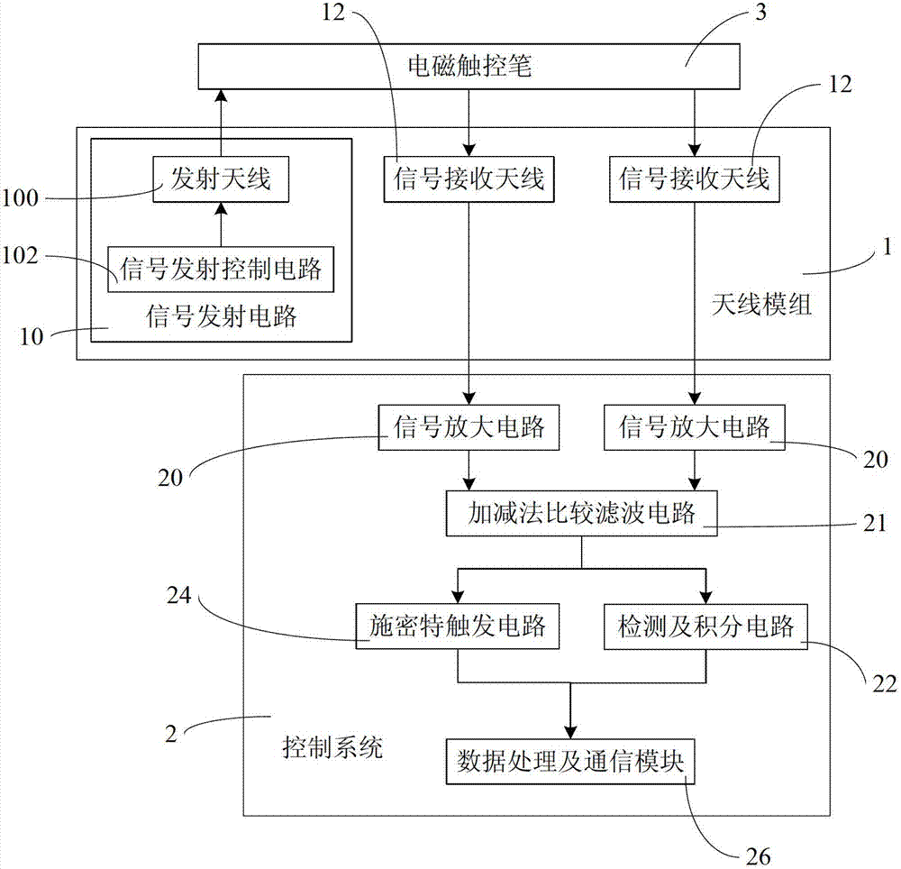
[0025] Such as figure 1 As shown, the present invention provides an electromagnetic touch device, comprising:

[0026] The antenna module 1, the antenna module 1 includes a signal transmitting circuit 10 for transmitting a control signal to the electromagnetic stylus 3 used in conjunction with it and a signal receiving antenna 12 for receiving the touch signal emitted by the electromagnetic stylus 2 , wherein, the signal transmitting circuit 10 includes a transmitting antenna 100 and a signal transmitting control circuit 102, the signal receiving antenna 12 is provided with two circuits, the same as the signal receiving antenna of the existing electromagnetic touch device, the signal r...


PUM


Abstract

The invention relates to an electromagnetic touch device. The electromagnetic touch device comprises an antenna module and a control system, wherein the antenna module comprises a signal transmitting circuit and signal receiving antennae; the control system is connected with the antenna module and comprises signal amplifying circuits, a filter circuit, a detection and integral circuit, a Schmidt trigger circuit and a data processing and communication module, wherein the filter circuit is connected with the signal amplifying circuits, performs filtering processing on an amplified signal and outputs two signals; two signal receiving antennae are provided, and each signal receiving antenna is provided with a signal amplifying circuit; and the filter circuit is an addition and subtraction comparison filter circuit which simultaneously performs the filtering processing on the touch signals which are received by the two signal receiving antennae and are amplified. The electromagnetic touch device can be matched with a passive electromagnetic stylus and can also be matched with an active electromagnetic stylus by arranging the signal transmitting circuit and the two signal receiving antennae on the electromagnetic touch device at the same time and matching the addition and subtraction comparison filter circuit.

Description

technical field [0001] The present invention relates to the technical field of touch control, in particular to an electromagnetic touch device. Background technique [0002] Touch control technology is more and more applied in the field of electronic products. At present, the mainstream touch screen technologies mainly include the following types: resistive, capacitive and inductive. Among them, the inductive touch screen can be divided into active and passive according to the working principle, and the active and passive are mainly for the electromagnetic stylus. [0003] Active electromagnetic touch devices can be called active electromagnetic touch devices. Its working principle is: the electromagnetic stylus actively emits electromagnetic signals, the antenna board receives the signals and transmits them to the control system, and then the control system amplifies and filters the signals After being processed by the MCU of the control system, the touch information is s...

Claims


Application Information

Patent Timeline
Patent Type & Authority Applications(China)
IPC IPC(8): G06F3/0354
Inventor 谢磊贺爱兰
Owner 贺爱兰
Why Eureka
Eureka Blog
Learn More