Plane structural part rib characteristic identification method

A technology for aircraft structural parts and identification methods, which is applied in special data processing applications, instruments, electrical digital data processing, etc., and can solve problems such as the inability to automatically identify the ribs of aircraft structural parts

Active Publication Date: 2013-02-13
NANJING UNIV OF AERONAUTICS & ASTRONAUTICS
View PDF1 Cites 6 Cited by
  • Summary
  • Abstract
  • Description
  • Claims
  • Application Information

AI Technical Summary

Problems solved by technology

[0008] The purpose of the present invention is to provide a method for identifying the tendon features of aircraft structural parts in view of the difficult problem that the tendon features of aircraft structural parts cannot be automatically identified

Method used


Image

  • Plane structural part rib characteristic identification method
  • Plane structural part rib characteristic identification method
  • Plane structural part rib characteristic identification method

Examples


Embodiment Construction

[0038] The technical solution of the present invention will be described in detail below in conjunction with the accompanying drawings.

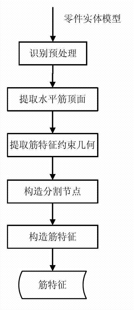
[0039] A rib feature recognition method for aircraft structural parts. Its new rib feature definition and specific identification process. The specific identification process includes identification preprocessing, horizontal rib top surface extraction, constraint geometric surface extraction, node structure segmentation, and rib feature definition. Extract rib features.

[0040] The new rib feature is defined as:

[0041] Rib feature (R) definition:

[0042] R=Geo∪Attr (1)

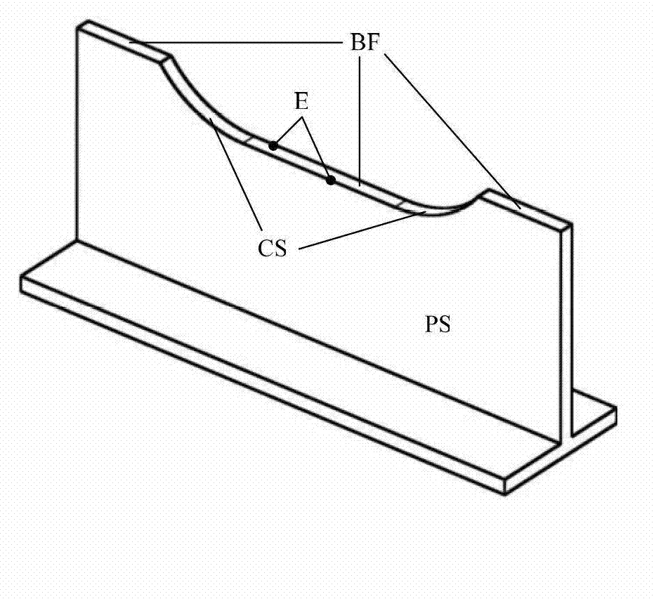
[0043] Geo=R top ∪R drive ∪R limit (2)

[0044] Geo represents the geometric information of the rib feature, where R top , R drive , R limit Respectively represent the rib top surface, feature boundary, and constraint geometry of the rib feature. The top surface of the rib is perpendicular to the Z direction of the processing coordinate ...


PUM


Abstract

The invention discloses a plane structural part rib characteristic identification method, and belongs to the technical fields of computer-aided design (CAD)/computer-aided process planning (CAPP)/computer-aided manufacturing (CAM). The method is composed of five mainly procedures which are identification pretreatment, horizontal rib top surface extraction, constraint geometric surface extraction, split node construction and rib characteristic extraction. The method can effectively achieve automatic extraction of rib characteristics of a plane structural part, and is high in the identification rate and efficiency. When the crossed rib characteristic identification is processed by the method, the purpose that time consumption caused by deceleration of a machine tool during processing of the rib characteristics is achieved, and the identification result can improve processing efficiency. When the method is used for numerical control programming based on the characteristics, high programming efficiency and high programming quality can be obtained, and good application prospect is achieved.

Description

technical field [0001] The invention relates to a rib feature recognition method of an aircraft structural part, and belongs to the technical field of CAD / CAPP / CAM. Background technique [0002] During the NC programming process of aircraft structural parts, it is necessary to manually pick up a large number of geometries, set a large number of parameters and create a large number of auxiliary geometries. The efficiency of NC programming is low and the quality is unstable. With the increase of integral parts, thin-walled parts and special material parts, the workload of NC programming has increased significantly, and the NC programming of aircraft structural parts has increasingly become one of the important bottlenecks affecting the aircraft development cycle. The feature-based NC programming technology takes features as the information carrier and can effectively integrate the knowledge and experience of machining technology, which is an important trend in the development ...

Claims


Application Information

Patent Timeline
Patent Type & Authority Applications(China)
IPC IPC(8): G06F17/50
Inventor 李迎光刘旭刘长青郝小忠王伟施建飞汤立民
Owner NANJING UNIV OF AERONAUTICS & ASTRONAUTICS
Why Eureka
Try Eureka