
Display panel driving device, operation method thereof and source electrode driver of display panel driving device

A technology of source driver and display panel, applied in the field of display panel drive device and source driver, can solve the problem of inability to judge the display data of the timing controller and the like

Inactive Publication Date: 2013-02-13
NOVATEK MICROELECTRONICS CORP
View PDF7 Cites 22 Cited by
  • Summary
  • Abstract
  • Description
  • Claims
  • Application Information

AI Technical Summary

Problems solved by technology

However, conventional source drivers cannot judge whether the display data received from the timing controller is correct or not

Method used


Image

  • Display panel driving device, operation method thereof and source electrode driver of display panel driving device
  • Display panel driving device, operation method thereof and source electrode driver of display panel driving device
  • Display panel driving device, operation method thereof and source electrode driver of display panel driving device

Examples


Embodiment Construction

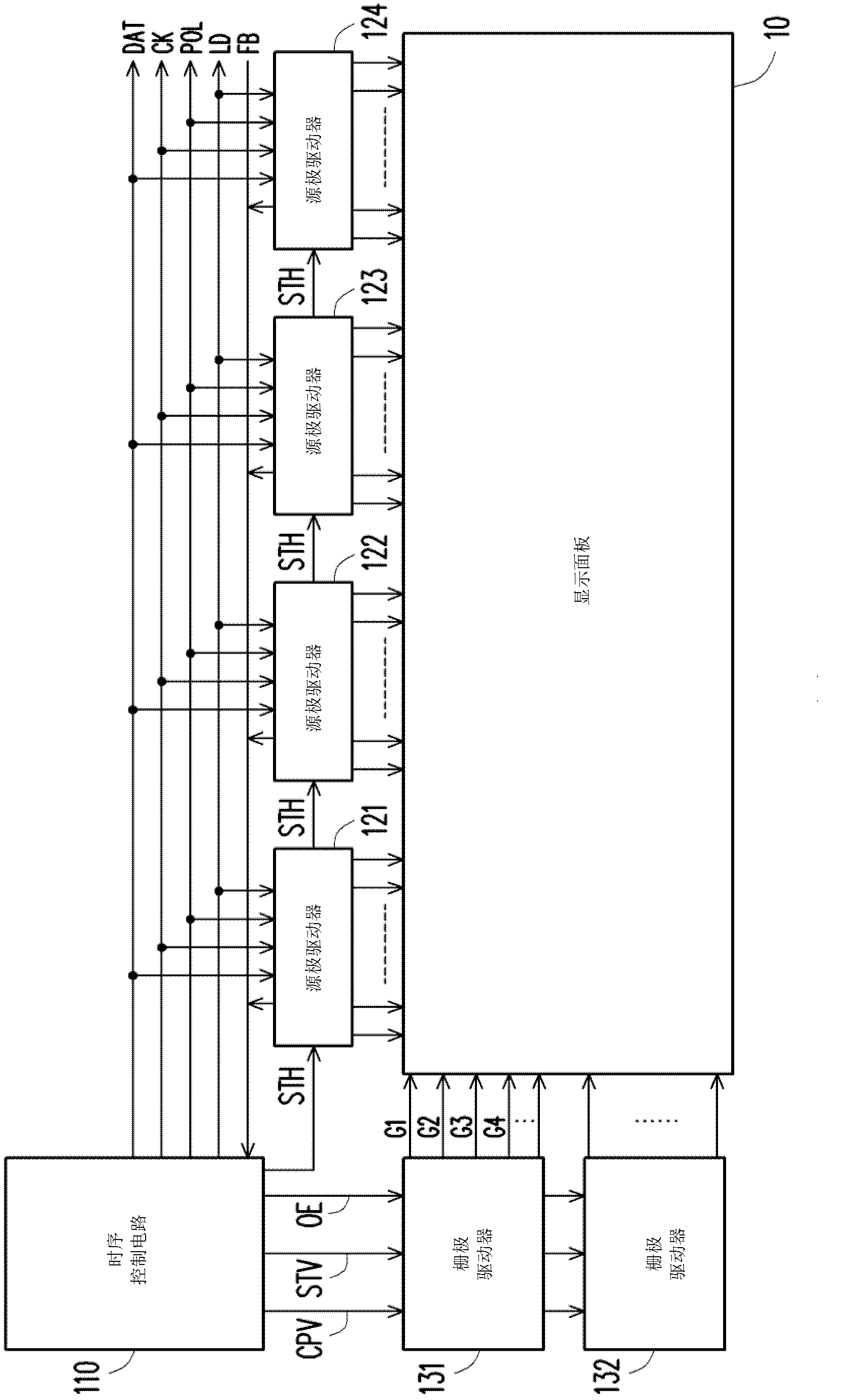
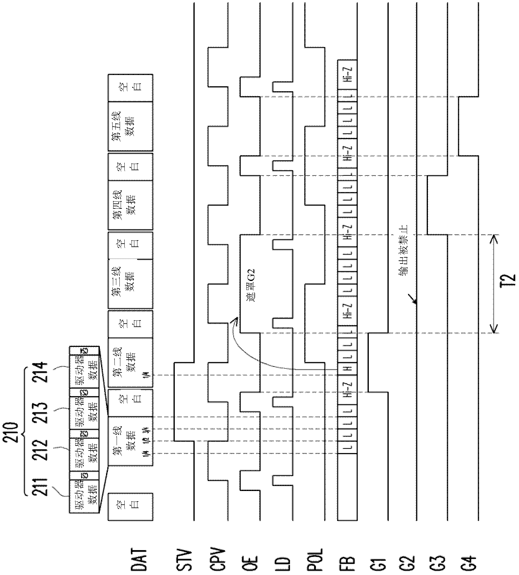
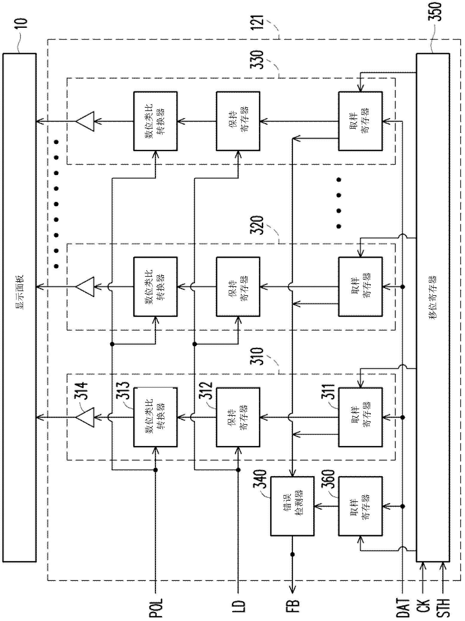
[0035] The present invention can be applied to any type of display driving device. E.g, figure 1 It is a functional block diagram illustrating a display panel driving device according to an embodiment of the present invention. The display panel driving apparatus includes a timing controller 110, at least one source driver (such as the source drivers 121, 122, 123, and 124), and at least one gate driver (such as the gate drivers 131 and 132). figure 2 According to the embodiment of the present invention figure 1 Schematic diagram of signal timing of the display panel driving device in. Various control signals will be described, but different control signals and driving mechanisms may be used in other embodiments of the present invention. Those of ordinary skill in the art can use any type of display driving device according to the design requirements, and use the teaching of the present invention figure 1 versus figure 2 The illustrated embodiment is analogously applied to the...


PUM


Abstract

The invention provides a display panel driving device, an operation method thereof and a source electrode driver of the display panel driving device. The display panel driving device comprises a time schedule controller and the source electrode driver, wherein the time schedule controller outputs display data and error checking data; and the source electrode driver generates source electrode driving signals for driving the display panel according to the display data provided by the time schedule controller, and checks whether the display data are wrong or not according to the error checking data provided by the time schedule controller. The display panel driving device can prevent wrong source electrode driving signals from being written into the display panel.

Description

Technical field [0001] The present invention relates to a display device, and more particularly to a display panel driving device, an operating method of the display panel driving device, and a source driver thereof. Background technique [0002] In the conventional display panel driving device, the data / control signal transmission between the timing controller and the source driver is only unidirectional, that is, from the timing controller to the source driver. The timing controller frequently transmits a large amount of display data to the source driver. During the transmission of display data from the timing controller to the source driver, various types of noise, such as electromagnetic interference (EMI), may change the display data. When the source driver receives wrong display data, the source driver will use the wrong source driving signal to drive the display panel. However, the conventional source driver cannot determine whether the display data received from the tim...

Claims


Application Information

Patent Timeline
Patent Type & Authority Applications(China)
IPC IPC(8): G09G3/20
Inventor 郭德献杨琇惠徐锦鸿
Owner NOVATEK MICROELECTRONICS CORP
Learn More