A method and device for detecting and processing sound cavity leakage
A sound cavity and sound source technology, applied in the field of communication, can solve the problem that the low-frequency resonance frequency of the sound cavity cannot be tested, and achieve the effect of preventing noise
- Summary
- Abstract
- Description
- Claims
- Application Information
AI Technical Summary
Problems solved by technology
Method used
Image

Examples
Embodiment 1
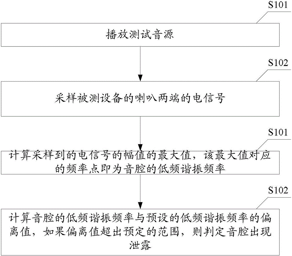
[0038] see figure 1 The method for detecting sound cavity leakage provided by Embodiment 1 of the present invention includes the following steps:
[0039] S101, play a test sound source;
[0040] In Embodiment 1 of the present invention, the test sound source is a test sound source stored in the device under test or a test sound source stored in a device connected to the device under test. The test sound source is a sweeping signal whose signal range covers the low-frequency resonance frequency. The sweeping signal is a combination signal of equal amplitude and multiple frequencies, and the frequency point is set according to the needs.
[0041] S102. Sampling electrical signals at both ends of the speaker of the device under test;
[0042] In the first embodiment of the present invention, step S102 is specifically to collect the output signal amplitudes at both ends of the speaker of the device under test at each frequency point; the two ends of the speaker refer to the two...
Embodiment 2
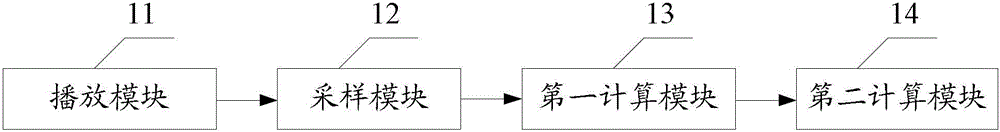
[0052] see figure 2 , the device for detecting sound cavity leakage provided by Embodiment 2 of the present invention includes:
[0053] Playing module 11, is used for playing test sound source;
[0054] In the second embodiment of the present invention, the test sound source is a test sound source stored in the device under test or a test sound source stored in a device connected to the device under test. The test sound source is a sweeping signal whose signal range covers the low-frequency resonance frequency. The sweeping signal is a combination signal of equal amplitude and multiple frequencies, and the frequency point is set according to the needs.
[0055] The sampling module 12 is used for sampling the electrical signal at both ends of the horn of the device under test;
[0056] In the second embodiment of the present invention, the sampling module 12 is specifically used to collect the output signal amplitude at each frequency point at both ends of the speaker of th...
Embodiment 3
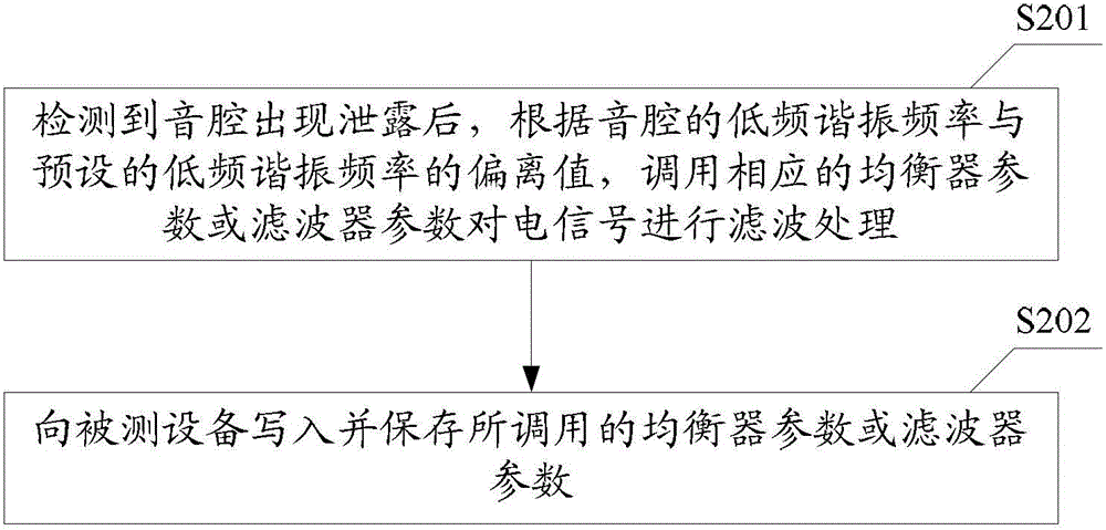
[0065] see image 3 The method for processing sound cavity leakage provided by Embodiment 3 of the present invention includes the following steps:
[0066] Step S201, when the leakage of the sound cavity is detected through the method for detecting sound cavity leakage provided by the second embodiment of the present invention, call the corresponding equalizer parameters according to the deviation value between the low-frequency resonance frequency of the sound cavity and the preset low-frequency resonance frequency Or filter parameters to filter the electrical signal to achieve the purpose of preventing noise, broken sound, and speaker burnout. Among them, the equalizer parameters or filter parameters are preset, and different deviation values correspond to different equalizer parameters or Filter parameters, different equalizer parameters or filter parameters can perform different degrees of filtering processing on the electrical signal, so as to achieve the purpose of n...
PUM
 Abstract
Description
Claims
Application Information
 - R&D
- Intellectual Property
- Life Sciences
- Materials
- Tech Scout
- Unparalleled Data Quality
- Higher Quality Content
- 60% Fewer Hallucinations
Browse by: Latest US Patents, China's latest patents, Technical Efficacy Thesaurus, Application Domain, Technology Topic, Popular Technical Reports.
© 2025 PatSnap. All rights reserved.Legal|Privacy policy|Modern Slavery Act Transparency Statement|Sitemap|About US| Contact US: help@patsnap.com