
Indwelling needle device

A technology of indwelling needles and external needles, applied in the direction of needles, instruments introduced into the body, catheters, etc.

Inactive Publication Date: 2015-02-25
JMS CO LTD
View PDF5 Cites 0 Cited by
  • Summary
  • Abstract
  • Description
  • Claims
  • Application Information

AI Technical Summary

Problems solved by technology

[0010] However, assuming that Figure 8 As shown in B, if the Figure 8 The outer peripheral surface of the outer needle 910 of the indwelling needle device shown in A forms a side hole 911, then there is the following problem: when puncturing to the patient's blood vessel, the patient's blood 930 enters the inner needle from the inner needle 920 through the side hole 921 of the inner needle 920. The gap 925 between the needle 920 and the outer needle 910 leaks out to the outside through the side hole 911 of the outer needle 910

Method used


Image

  • Indwelling needle device
  • Indwelling needle device
  • Indwelling needle device

Examples


Embodiment Construction

[0030] In the above-mentioned indwelling needle device of the present invention, it is preferable that, when the bush is at the initial position, the inner peripheral surface of the outer needle and the outer peripheral surface of the inner needle are in close contact with the aforementioned region. On the sheath side, a gap is formed between the inner peripheral surface of the outer needle and the outer peripheral surface of the inner needle, and the second side hole passes through the gap and the space between the outer surface of the bush and the inner surface of the sheath. connected. Thus, when the bush is in the initial position, through the second side hole, in addition to the gap between the inner needle and the outer needle, the space between the outer surface of the bush and the inner surface of the sheath can be easily used. Blood filled priming operation.

[0031] Preferably, when the bush is at the initial position, the first side hole does not communicate with t...


PUM


Abstract

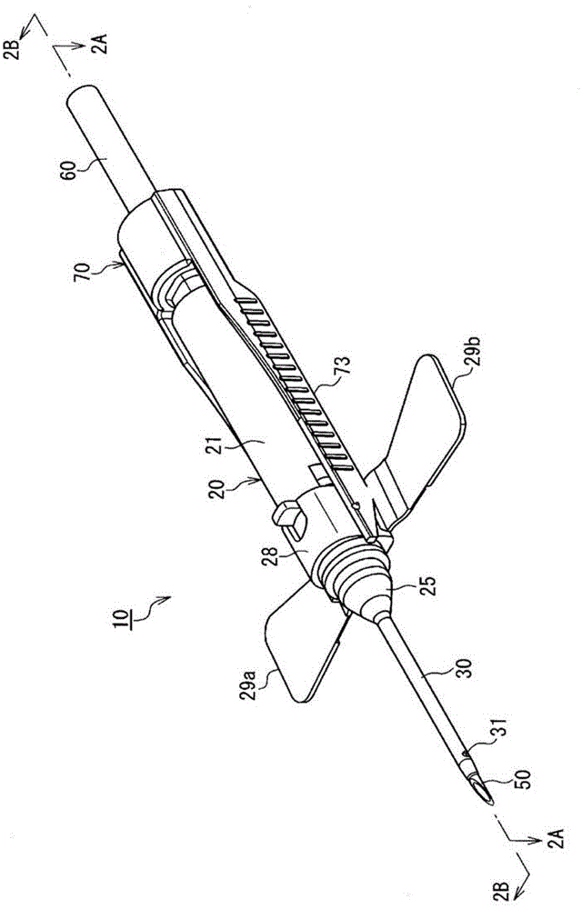
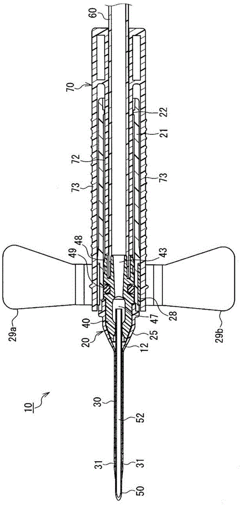
When a hub (40) is in an initial position at which it is located on the front end side of an inner cavity of a shield (20), an inner needle (50) penetrates an outer needle (30) and protrudes from a leading end of the outer needle to the outside, and when the hub is in a retracted position at which it is located on the rear end side of the inner cavity of the shield, the inner needle is housed within the inner cavity of the shield. A first side hole (31) is formed in an outer circumferential face of the outer needle, and a second side hole (51) is formed in an outer circumferential face of the inner needle. When the hub is in the initial position, an inner circumferential face of a region (33) of the outer needle that contains the first side hole is in close contact with the outer circumferential face of the inner needle, and the second side hole is located closer to the hub than the region where the inner circumferential face of the outer needle is in close contact with the outer circumferential face of the inner needle. Thus, a priming operation for filling a gap between the inner needle and the outer needle with blood can be easily performed, and leakage of blood through the side hole of the outer needle during puncture does not occur.

Description

technical field [0001] The present invention relates to an indwelling needle device that includes a soft outer needle and a hard inner needle, and is configured to be able to puncture up to The patient, then retracts the inner needle from the outer needle. Background technique [0002] Indwelling needle devices are widely used for infusion, blood transfusion, extracorporeal blood circulation and other treatments. If the metal needle is placed in the blood vessel, it may stab the blood vessel. Therefore, a kind of indwelling needle device is described in Patent Document 1, which is equipped with a soft outer needle and a hard inner needle. The patient's blood vessel is punctured with the front end protruding from the front end of the outer needle, and then the inner needle is retracted from the outer needle. [0003] Figure 8 A is a cross-sectional view showing the tip of the inner needle 920 protruding from the tip of the outer needle 910 and its vicinity in the indwellin...

Claims


Application Information

Patent Timeline
Patent Type & Authority Patents(China)
IPC IPC(8): A61M5/158
CPCA61M25/0606A61M25/0631A61M5/158
Inventor 伊藤亨藤井亮至
Owner JMS CO LTD
Learn More