
Electric brake apparatus for vehicle

A brake device and electric brake technology, applied in the direction of brake transmission, brakes, vehicle components, etc., can solve the problems of cumbersome and complicated drive control, and achieve the effects of saving energy, simplifying drive control, and suppressing slipping

Inactive Publication Date: 2013-02-13
TOYOTA JIDOSHA KK
View PDF9 Cites 16 Cited by
  • Summary
  • Abstract
  • Description
  • Claims
  • Application Information

AI Technical Summary

Problems solved by technology

[0006] However, in the above-mentioned conventional electric brake control device, control method, and electric brake device, in order to ensure an appropriate gap between the brake rotating body and the brake friction body, the driving motor and the electric unit during braking are At the same time, for example, it is necessary to control the inverter circuit, etc. to drive the motor and the electric unit extremely finely, and the drive control becomes complicated and cumbersome
In addition, in order to ensure the gap, it is necessary to supply electric power to the motor and the electric unit, and there is still room for improvement from the viewpoint of energy saving.

Method used


Image

  • Electric brake apparatus for vehicle
  • Electric brake apparatus for vehicle
  • Electric brake apparatus for vehicle

Examples


no. 1 approach

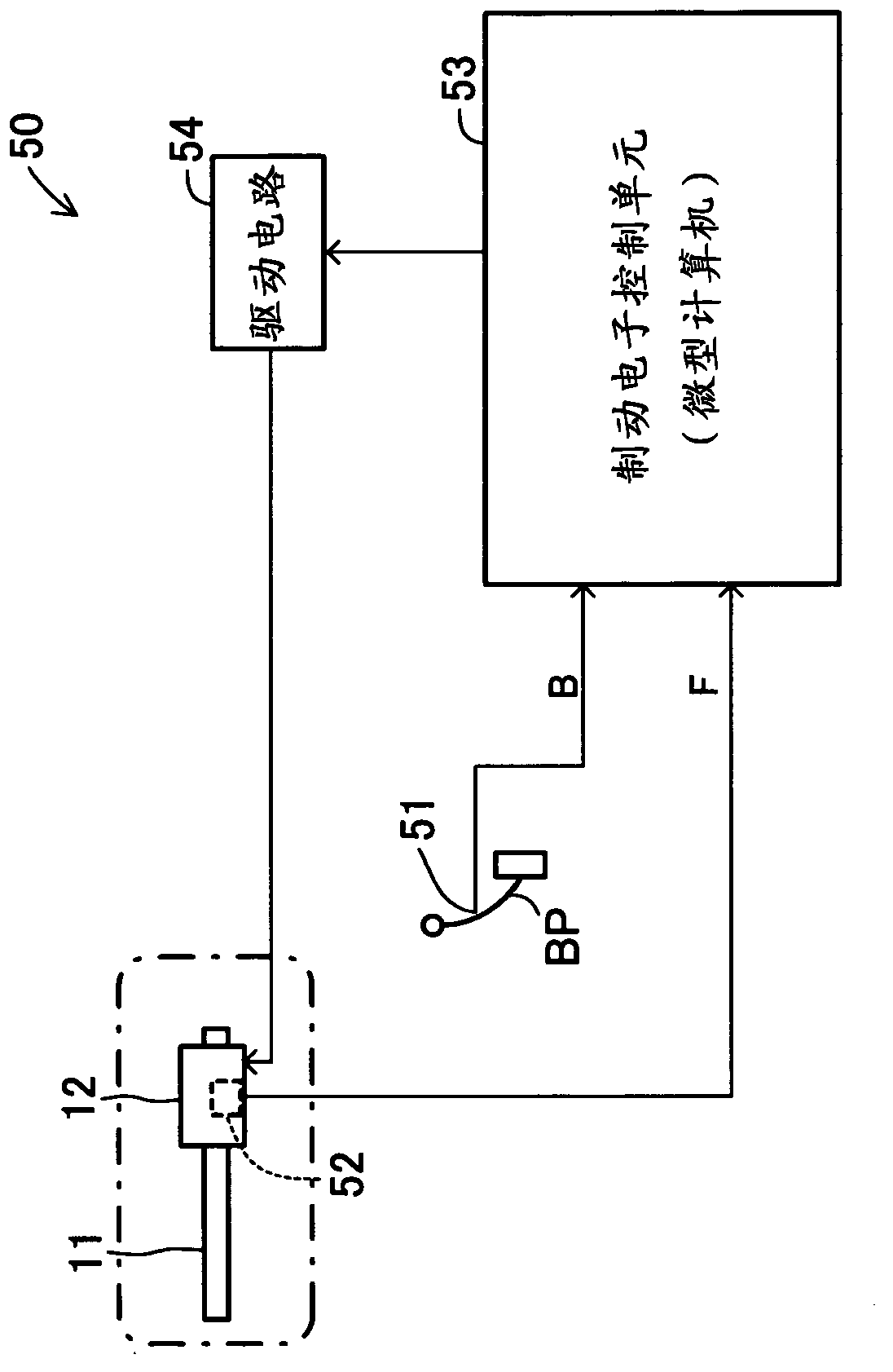
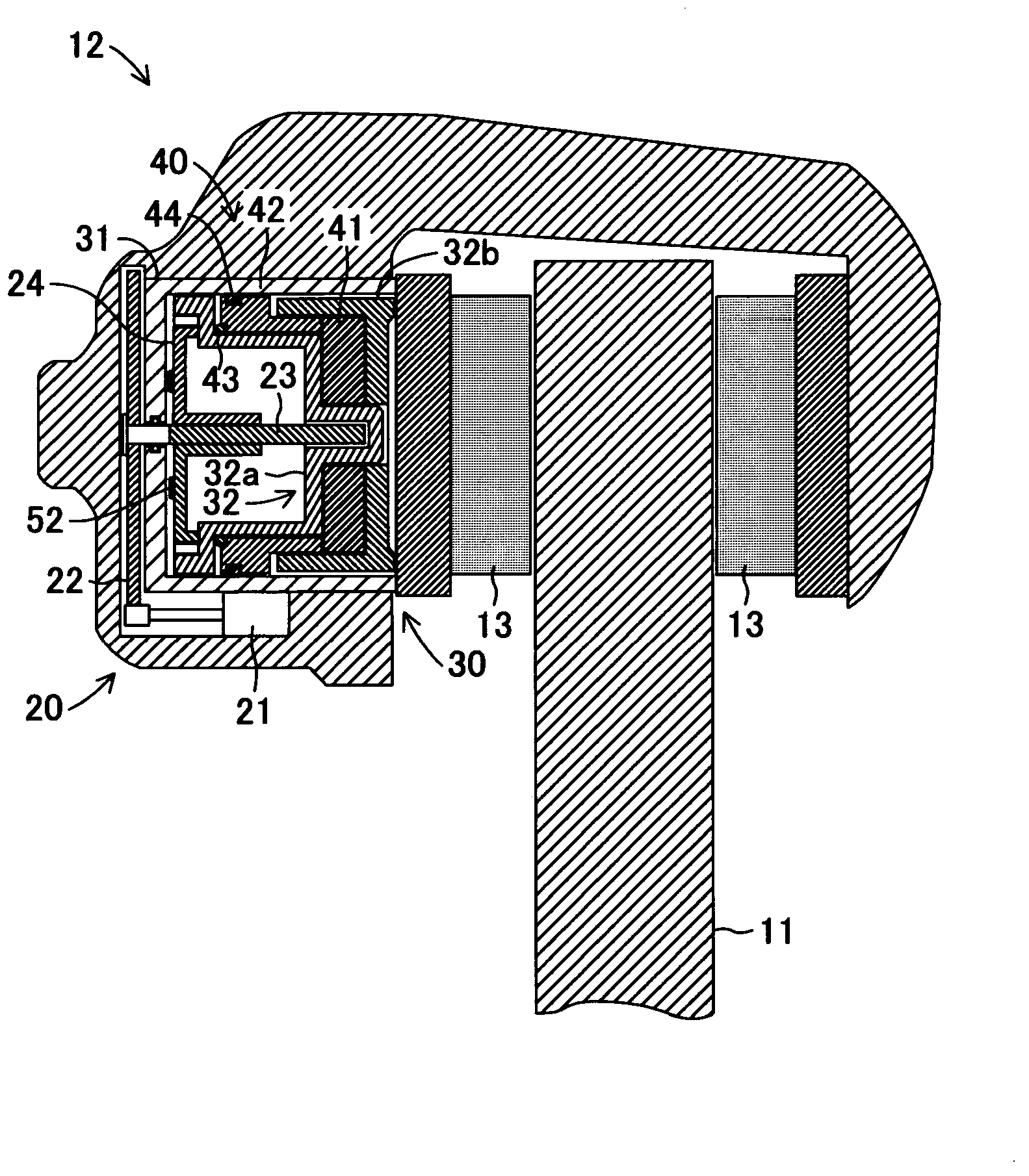
[0044] Hereinafter, embodiments of the present invention will be described in detail using the drawings. figure 1 The electric brake device according to the first embodiment of the present invention is schematically shown.

[0045] This electric brake device includes: a brake pad rotor 11 as a brake rotating body, the brake pad rotor 11 rotates around the rotation axis of the axle integrally with the wheel; and an electric brake caliper 12, the electric brake caliper 12 is supported by an unillustrated bracket fixed to the vehicle body side, and is movable along the rotation axis direction of the pad rotor 11 . In addition, in figure 1 Although only one wheel of the vehicle is schematically shown in FIG. 1 , it goes without saying that it can be implemented by providing electric braking devices on, for example, the left and right front wheel sides of the vehicle, the left and right rear wheel sides of the vehicle, or all the wheels.

[0046] The electric brake caliper 12 is ...

no. 2 approach

[0095] In the first embodiment described above, the brake ECU 53 controls the drive of the brake motor 21 in response to the brake operation of the pedal BP by the driver to apply a braking force to the rotating wheels. In this case, when applying the braking force to the rotating wheel, it can also be implemented in the same way as the known braking device: the hydraulic pressure (hydraulic pressure) of the brake fluid is used to advance the piston and press the friction pad On the friction sliding surface of the pad rotor, the electric brake device operates as a so-called electric parking brake device that brakes the rotation of the wheels when the vehicle is parked and stopped. Hereinafter, this second embodiment will be described in detail, but the same parts as those in the above-mentioned first embodiment will be given the same reference numerals and their descriptions will be omitted.

[0096] In this second embodiment, the brake fluid whose hydraulic pressure is adjust...


PUM


Abstract

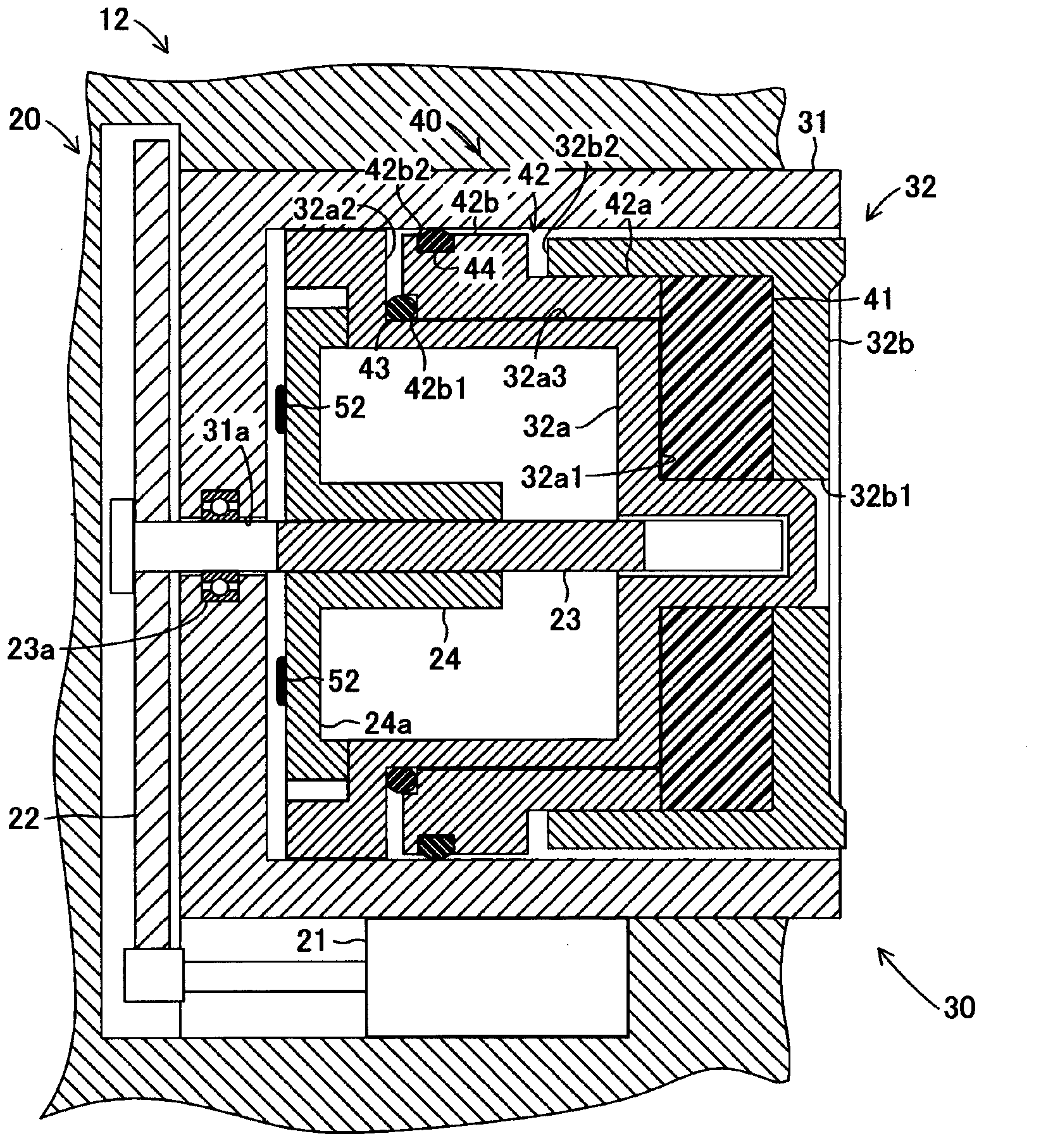
Disclosed is an electric brake apparatus for a vehicle, wherein an electric caliper (12) is provided with an electric drive mechanism (20) for generating a pressing force for pressing a friction pad (13) against a disk rotor (11), and a retraction mechanism (40) provided in a piston (32) of a pressing mechanism (30). The retraction mechanism (40) is provided with a reversing member (41) which is compressed by a power transmission portion (32a) and a pressing portion (32b) of the piston (32), to generate a reversing force. Furthermore, the retraction mechanism (40) is provided with a movable element (42) which relatively moves backward by the reversing force, and a first elastic member (43) which is compressed by the movable element (42) and the forward moving power transmission portion (32a), to apply a restoring force. Thus, in the retraction mechanism (40), the reversing member (41) generates a reversing force in conjunction with the forward movement of the power transmission portion (32a), and the movable element (42) relatively moves backward, to compress the first elastic member (43). When a free rotation (no-load rotation) of a brake motor (21) which is a component of a mechanism (20) is allowed, the restoring force generated by the compression of the first elastic member (43) is applied to the power transmission portion (32a), to move the piston (32) backward.

Description

technical field [0001] The present invention relates to an electric brake device for a vehicle including a brake rotor that rotates integrally with a wheel, and an electric brake caliper that presses a brake friction member toward the brake rotor by electromotive force. Background technique [0002] Conventionally, for example, an electric brake control device and an electric brake control method disclosed in Japanese Patent Application Laid-Open No. 2008-57642 are known. In this conventional electric brake control device and control method, when the brake friction body satisfies a preset condition, the brake friction body is set between a predetermined first energization amount and a second energization amount smaller than the first energization amount. The amount of energization to the motor is gradually decreased, and the standby position of the brake friction body is set based on the rotational speed of the motor during the gradually decreased control. Accordingly, slip...

Claims


Application Information

Patent Timeline
Patent Type & Authority Applications(China)
IPC IPC(8): F16D65/18B60T13/74
CPCF16D2125/40B60T13/588F16D65/18F16D2123/00B60T13/741F16D2121/06B60T13/745F16D2127/02F16D2121/24
Inventor 矶野宏
Owner TOYOTA JIDOSHA KK
Learn More