
Motor-controlled hydraulic braking system

A technology of hydraulic braking and motor control, which is applied in the direction of braking safety systems, brakes, and braking transmission devices. It can solve the problems of motor hysteresis, up and down movement, etc., and achieve failure protection, improve response time, and maintain pressure. Effect

Active Publication Date: 2018-07-20
JILIN UNIV
View PDF6 Cites 0 Cited by
  • Summary
  • Abstract
  • Description
  • Claims
  • Application Information

AI Technical Summary

Problems solved by technology

[0005] The technical problem to be solved by the present invention is to provide a hydraulic brake system controlled by a motor in order to overcome the hysteresis effect caused by the motor in the commutation and overcome the problem of the brake pedal moving up and down caused by the change of the pedal force

Method used


Image

  • Motor-controlled hydraulic braking system
  • Motor-controlled hydraulic braking system
  • Motor-controlled hydraulic braking system

Examples


Embodiment Construction

[0031] The present invention is described in detail below in conjunction with accompanying drawing:

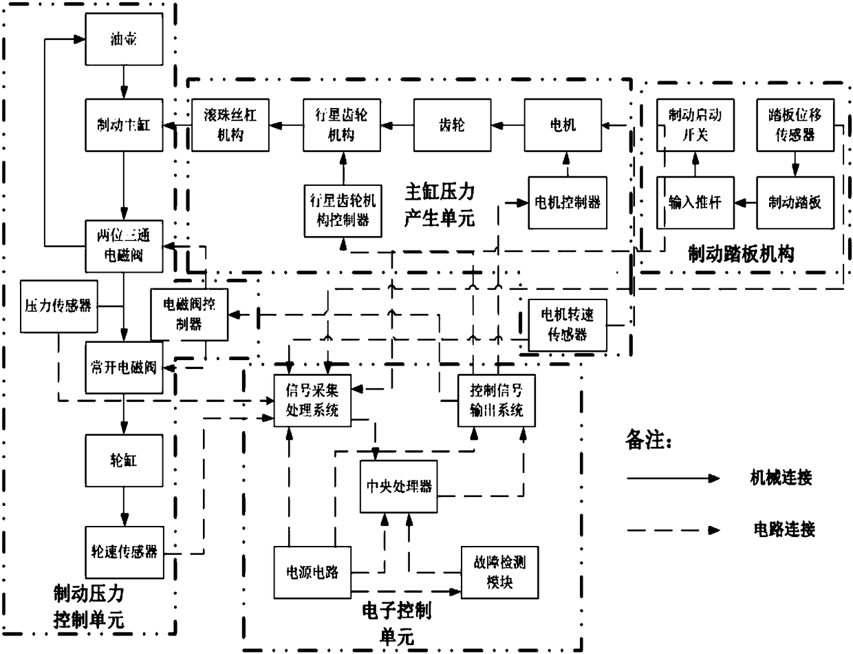
[0032] refer to figure 1 , The motor-controlled hydraulic brake system of the present invention includes a brake pedal mechanism, a master cylinder pressure generating unit, a brake pressure control unit and an electronic control unit.

[0033] The brake pedal mechanism includes a brake pedal 1, an input push rod 6, a brake activation switch, a pedal displacement sensor 16 and the like.

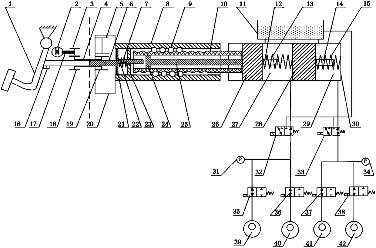
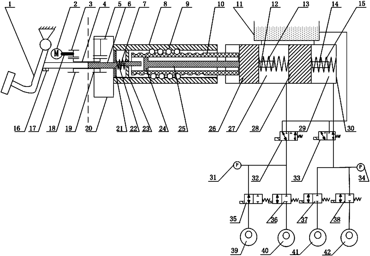
[0034] The top end of the brake pedal 1 is installed on the vehicle body for rotational connection, the upper end of the brake pedal 1 is rotationally connected with the left end of the input push rod 6, and the input push rod 6 is loaded into the hollow gear shaft 4 of the master cylinder pressure generating unit Inside, the right end of the input push rod 6 protrudes from the circular through hole at the center of the ring gear 20 on the right side of the gear shaft 4; the pedal displaceme...


PUM


Abstract

The invention discloses a motor-controlled hydraulic braking system. The problem that the hysteresis influence caused by a motor during direction shifting and vertical movement caused by the condition that a brake pedal changes with pedal force are solved. The motor-controlled hydraulic braking system comprises a brake pedal mechanism, a master cylinder pressure generating unit, a brake pressure control unit and an electronic control unit. The brake pedal mechanism comprises an input push rod (6); the master cylinder pressure generating unit comprises a ball screw mechanism; the brake pressure control unit comprises a brake master cylinder; and the electronic control unit comprises a control signal output system and a signal collecting treatment system. The brake pedal mechanism is fixedly connected with an input push rod limiting plate (21) in the ball screw mechanism through the input push rod (6), the master cylinder pressure generating unit is fixedly connected with a master cylinder front cavity piston (26) in the brake master cylinder through a connecting shaft (25) in the ball screw mechanism, and the electronic control unit is connected with the brake pedal mechanism, the master cylinder pressure generating unit and the brake pressure control unit in an electric wire mode.

Description

technical field [0001] The invention relates to a brake system belonging to automobile safety, more precisely, the invention relates to a motor-controlled hydraulic brake system. Background technique [0002] With the continuous development of the automobile industry, various automobile technologies have made continuous breakthroughs and progress. As an important and core part of automobile safety, the automobile braking system plays a particularly important role in the development and breakthrough of automobiles. On the basis of traditional hydraulic braking, the automobile braking system is constantly developing towards wire-controlled hydraulic braking. The traditional hydraulic braking system is mainly assisted by a vacuum booster, which has relatively insufficient response time and control accuracy to the braking pressure; moreover, it is relatively bulky and expensive. [0003] Bosch's i-Booster (integrated booster) system integrates the motor and the brake master cy...

Claims


Application Information

Patent Timeline
Patent Type & Authority Patents(China)
IPC IPC(8): B60T13/66B60T13/68B60T7/06B60T17/22
CPCB60T7/06B60T13/66B60T13/686B60T17/22
Inventor 李静王晨夏承贺
Owner JILIN UNIV
Learn More