Eureka AIR delivers breakthrough ideas for toughest innovation challenges, trusted by R&D personnel around the world.

Gear axis position adjustable mechanism

A shaft center and idler shaft technology, applied in the field of transmission, can solve the problem that the position of the idler shaft cannot be changed, and achieve the effects of improving assembly accuracy and transmission accuracy, reducing the number of disassembly and assembly, and prolonging the service life

Inactive Publication Date: 2013-02-20
CHINA NORTH ENGINE INST TIANJIN
View PDF3 Cites 9 Cited by
  • Summary
  • Abstract
  • Description
  • Claims
  • Application Information

AI Technical Summary

Problems solved by technology

[0004] In order to overcome the technical problem that the position of the axis of the idler wheel cannot be changed in the prior art, the invention improves the axis of the idler wheel and designs an adjustable mechanism for the axis of the idler wheel

Method used


Image

  • Gear axis position adjustable mechanism
  • Gear axis position adjustable mechanism
  • Gear axis position adjustable mechanism

Examples


Embodiment Construction

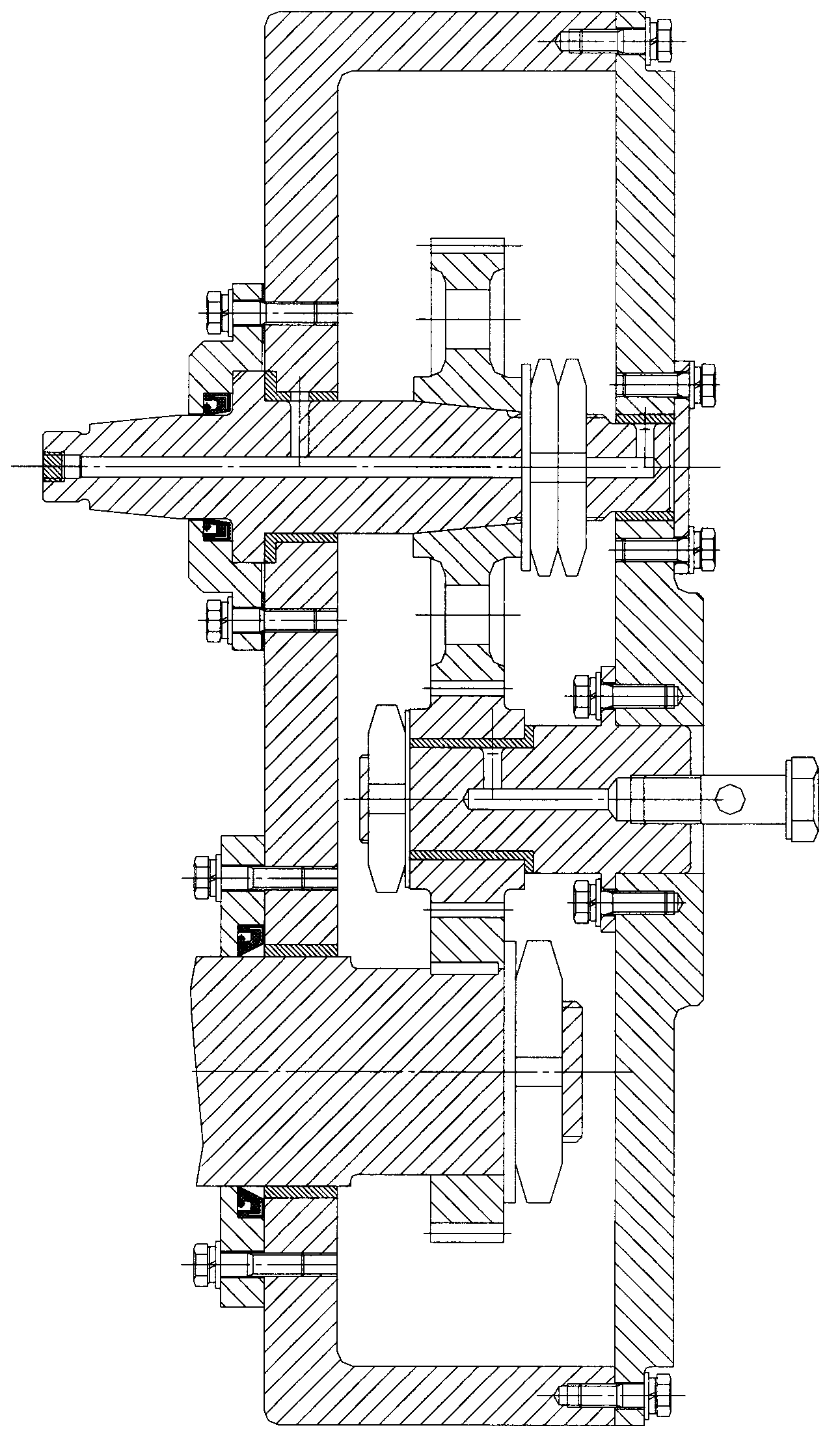
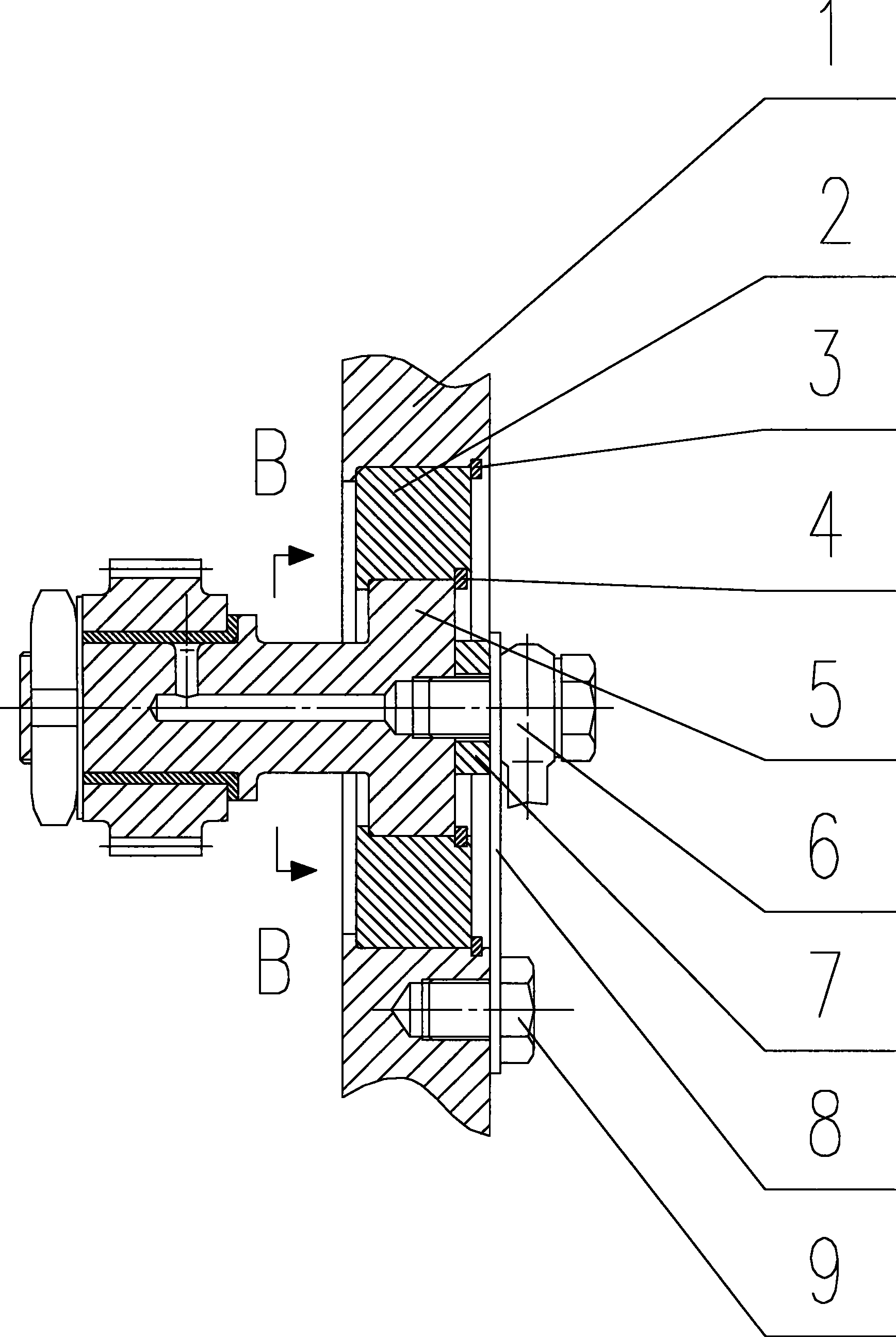
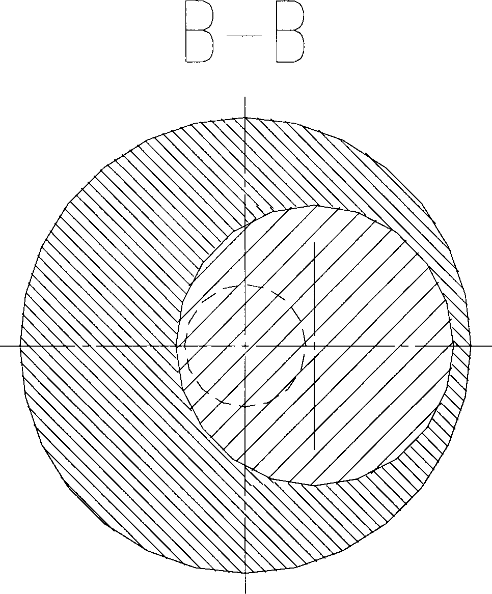
[0026] combined with figure 2 The gear axis position adjustable mechanism is specifically described: a large stepped through hole is processed at the installation part of the idler shaft of the transmission box cover 1. The radius of the large stepped through hole close to the inside of the transmission box is R1, and the radius close to the outside of the transmission box is R2. R2>R1; there is a large retaining ring groove at the large radius of the large stepped through hole, and the distance between the side wall of the large retaining ring groove near the variable diameter of the large stepped through hole and the variable diameter of the large stepped through hole is L1; another radius is processed R2, a large circular plate 2 with a thickness of L1, with an eccentric small stepped through hole on the large circular plate 2, the eccentric distance between the center of the large circular plate 2 and the small stepped through hole is L3, and the radii of the small stepped...


PUM


Abstract

The invention belongs to the transmission field and particularly relates to a gear axis position adjustable mechanism which comprises a gear box cover 1, a large round plate 2, a small round plate 5, an idler shaft, a large check ring 3, a small check ring 4 and a fixing mechanism, wherein a large step through hole is arranged on the gear box cover, the hole diameter of the large step through hole close to the interior of a gear box is small than that of the large step through hole close to the exterior of the gear box, a large check ring groove is arranged on the hole wall of the large step through hole close to the exterior of the gear box, and the large check ring 3 is arranged in the large check ring groove. The gear axis position adjustable mechanism can achieve fine adjustment of the transmission gear axis position, is simple and reliable in action, improves assembling accuracy and transmission accuracy of a transmission gear, and prolongs service life of the transmission gear. For a gear transmission mechanism in research and development, the gear axis position adjustable mechanism enables the gear transmission axis central position to be adjusted randomly in a certain range, can reduce the mounting and demounting times of an engine, and meets requirements of different transmission ratios.

Description

technical field [0001] The technical field of the present invention is the transmission field, especially a mechanism capable of realizing the adjustable position of the shaft center of the gear. Background technique [0002] Gear transmission mechanism is one of the most widely used mechanisms in the machinery industry. In the engine industry, the gear transmission mechanism is widely used in the transmission mechanism and is an indispensable part of the engine transmission mechanism. [0003] After the design of a set of gear transmission mechanism is completed, the center distance of each gear is difficult to change due to the meshing requirements between each gear. But for the engine under development, due to the new transmission ratio design requirements, some transmission gears in the transmission mechanism may need to be readjusted. For example, if the number of teeth of a gear needs to be increased, the diameter of its pitch circle will become larger, and the posit...

Claims


Application Information

Patent Timeline
Patent Type & Authority Applications(China)
IPC IPC(8): F16H57/022
Inventor 康彦红徐春龙李晓娟李云广蔡中周
Owner CHINA NORTH ENGINE INST TIANJIN
Why Eureka
Eureka Blog
Learn More