Car shift level structure and car
A shift lever and shift mechanism technology, applied to vehicle parts, components with teeth, control devices, etc., can solve the problem of non-adjustable shift handle height, increased seat design complexity, and different control experience and other issues, to achieve the effect of reducing R&D costs, occupying a small space, and improving comfort and safety
- Summary
- Abstract
- Description
- Claims
- Application Information
AI Technical Summary
Problems solved by technology
Method used
Image


Examples
Embodiment 1
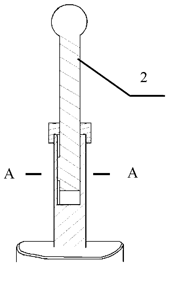
[0026] Such as figure 1 , 2 As shown, the car shift lever structure in this embodiment includes a shift handle 1 , a shift connecting rod, and a mounting plate 5 . Wherein, the shift linkage includes an upper linkage 2, a lower linkage 4 and a fixing mechanism.
[0027] One end of the mounting plate 5 is connected with the lower end of the lower connecting rod 4, and its other end is connected with the shift mechanism, that is, the lower end of the lower connecting rod 4 is connected with the gear shift mechanism through the mounting plate 5.
[0028] The upper end of the upper connecting rod 2 is fixedly connected to the shift handle 1, and its lower end can be sleeved at different height positions of the lower connecting rod 4. The fixing mechanism is used to fix the upper connecting rod 2 on the lower connecting rod 4. At different height positions, that is, the upper connecting rod 2 and the lower connecting rod 4 are fixed by the fixing mechanism.
[0029] Such as im...
Embodiment 2
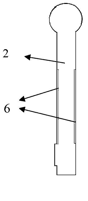
[0035] The difference between the structure of the automobile shift lever in this embodiment and that of Embodiment 1 lies in that the structures of the upper connecting rod 2 and the lower connecting rod 4 are different.
[0036] In this embodiment, no protrusion is provided on the upper connecting rod 2 , and no groove is provided on the lower connecting rod 4 .
[0037] Specifically, the upper connecting rod 2 is cylindrical, and the upper connecting rod 2 is provided with a first external thread 6, and the first external thread 6 extends along the axial direction of the upper connecting rod 2; the lower connecting rod 4 is Hollow cylindrical, the upper connecting rod 2 can extend into the lower connecting rod 4, the outer wall of the lower connecting rod is provided with a second external thread 7, and the second external thread 7 starts from the upper end of the lower connecting rod 4 Extend down.
[0038] Wherein, the fixing mechanism includes a fixing nut 3, and the in...
PUM
 Abstract
Description
Claims
Application Information
PatSnap Eureka turns technology decisions into work you can execute. Powered by our Innovation Knowledge Graph, it runs expert workflows across engineering, life sciences, materials and intellectual property. Get your review-ready output in minutes.


