Lamp base of anti-explosion fluorescent lamp fitting

A technology for lamp pins and lamps, which is applied to the anti-damage measures of lighting devices, lighting devices, parts of lighting devices, etc., and can solve the problems of unsightly appearance, protruding ribs are easy to get stuck on cross holes, springs are easy to rust and damage, etc. problems, achieve good self-installation performance, ensure initial installation efficiency, and prevent rust damage

Inactive Publication Date: 2014-04-16
陆阳 +1
View PDF6 Cites 0 Cited by
  • Summary
  • Abstract
  • Description
  • Claims
  • Application Information

AI Technical Summary

Problems solved by technology

[0007] When installing the explosion-proof lamp pins of the above-mentioned explosion-proof fluorescent lamps, the spring is compressed, and the force is slightly uneven. Only when the position of the socket is adjusted can it be reinstalled
In addition, when the above-mentioned light tube socket is inserted into the cross hole, the spring needs to be compressed to a very short position to avoid the convex rib, and the convex rib is easily stuck on the cross hole, making it difficult to complete the insertion.
Since the connection between the lamp socket and the lamp holder only depends on the pressure of the spring, it is actually still a movable connection. When the whole lamp is shaken, the lamp socket is easy to come out and the lamp falls off.
[0008] Moreover, the springs of the lamp pins of the above-mentioned explosion-proof fluorescent lamps are exposed outside. Since the explosion-proof lamps are often in a corrosive gas environment, the springs are easily rusted and damaged, and the appearance is not beautiful; , so that the volume of the lamp socket is relatively large, correspondingly, the number of lamp tubes that can be arranged on the lamp base is limited

Method used


Image

  • Lamp base of anti-explosion fluorescent lamp fitting
  • Lamp base of anti-explosion fluorescent lamp fitting
  • Lamp base of anti-explosion fluorescent lamp fitting

Examples


Embodiment Construction

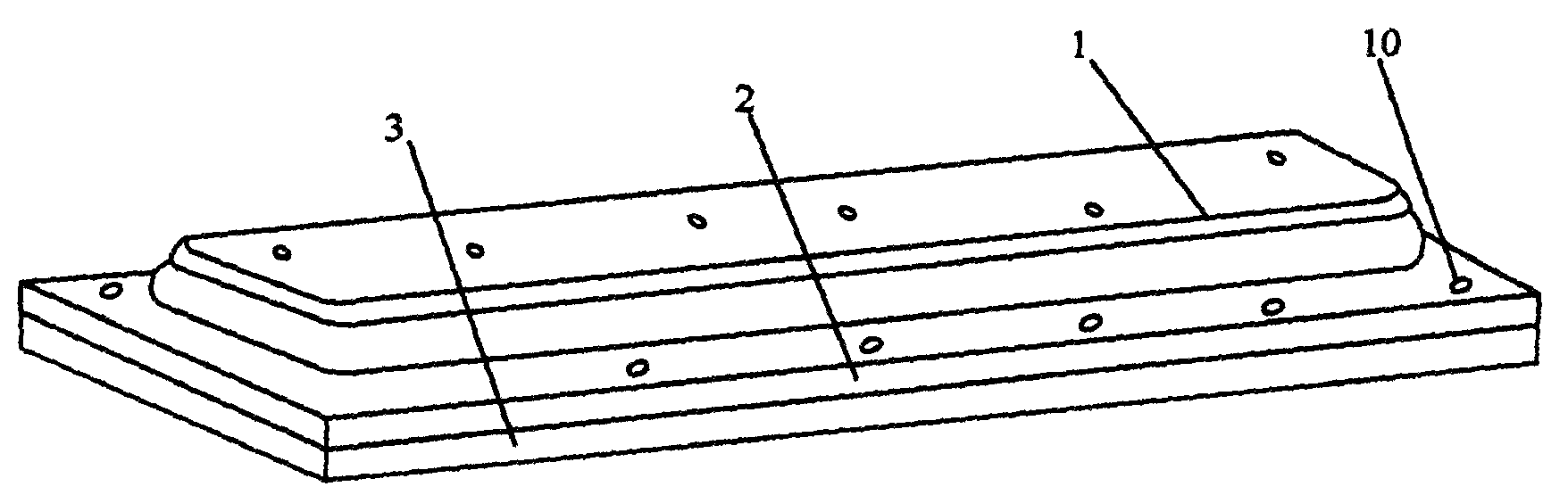
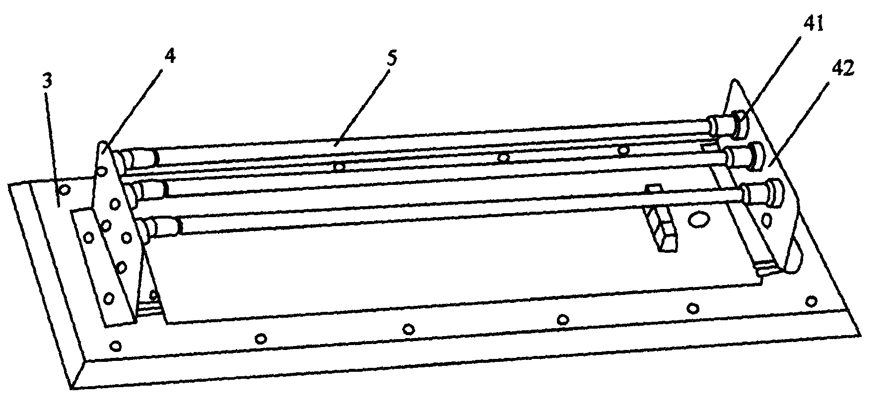
[0036] like figure 1 , figure 2 , an explosion-proof fluorescent lamp, including a lampshade 1, a lamp cover 2 and a base 3 that are detachably connected in sequence, a lamp holder (omitted in the figure) is arranged on both sides of the base 3, and a lamp foot 4 is arranged on the lamp holder.

[0037] At least one explosion-proof lamp tube 5 installed on the lamp pin 4, usually three.

[0038] A reflector (omitted in the figure) is arranged between the base 3 and the explosion-proof lamp tube 5 . The lampshade 1, the lamp cover 2, the base 3 and the reflector are all provided with a plurality of connecting pieces 10 for installation, and the connecting pieces 10 are commonly used with screws, bolts and the like. Electrical components such as ballasts are placed in the gap between the reflector and the base 3 .

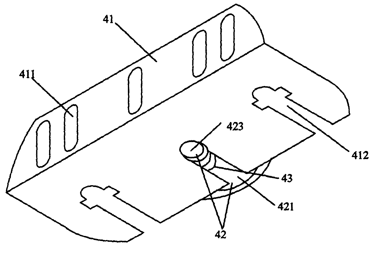
[0039] like Image 6 , Figure 7 The lamp pin of the explosion-proof fluorescent lamp of the present invention includes a lamp base 41 connected to the lamp fr...


PUM


Abstract

The invention relates to a lamp fitting structure, and in particular relates to a lamp base of an anti-explosion fluorescent lamp fitting. The lamp base of the anti-explosion fluorescent lamp fitting comprises a lamp base seat, a lamp tube socket and a socket cover, wherein the lamp base seat is connected with a lamp frame; the lamp tube socket is detachably arranged on the lamp base seat; the lamp base seat is composed of two panels which can form an angle; the first panel is connected with the lamp frame and is provided with a plurality of positioning holes; the second panel is provided with the lamp tube socket; a plurality of socket holes are formed in the second panel; a pair of installation holes are respectively formed in two sides of each socket hole; the lamp tube socket comprises a lamp base end surface and a hand pull end surface which are sequentially connected by a socket post; the socket post is of a circular tube shape and is internally provided with a through hole, and a spring is arranged on the socket post in a penetrating way; the socket cover is of a circular tube shape; a flange is formed at one end (toward the circle center) of the socket cover; a pair of installation lugs are arranged at two sides of the outer wall of the socket cover; and holes are formed in each installation lug; the lamp tube socket is inserted into the socket cover, and the end surface of the lamp base is clamped in the flange of the socket cover; the hand pull end surface passes through the socket holes; and the installation lugs and the installation holes are connected through connecting parts.

Description

technical field [0001] The invention relates to a lamp structure, in particular to a lamp foot of an explosion-proof fluorescent lamp. Background technique [0002] Explosion-proof fluorescent lamps installed with fluorescent tubes are widely used in chemical industry, medicine, biotechnology, electronics, food, military industry, petroleum and other fields that require explosion-proof and dust-proof fluorescent lighting. The basic structure of explosion-proof fluorescent lamps is as follows: figure 1 , including a light-transmitting lampshade 1 , a lamp cover 2 and a base 3 . [0003] Lamp holders (omitted in the figure) are arranged on both sides of the base 3, and two lamp pins 4 are respectively arranged on the lamp holders. After removing lampshade 1 and lamp cover 2, if figure 2 As shown, a plurality of explosion-proof lamp tubes 5 are inserted on the lamp pins 4 , and a reflector (omitted in the figure) is arranged between the base 3 and the explosion-proof lamp t...

Claims


Application Information

Patent Timeline
Patent Type & Authority Patents(China)
IPC IPC(8): F21V21/00F21V23/06F21V15/00
Inventor 陆阳陆国富
Owner 陆阳
Why Eureka
Try Eureka