Installation device and method for arc-second-level three-dimensional optical deformation measurement device

A technology of three-dimensional optics and measuring devices, which is applied in the direction of using optical devices, measuring devices, instruments, etc., can solve the problem of the decrease of deformation measurement accuracy, the difficulty of achieving temperature stability and structural stability, and the lack of special precision installation devices and methods for each component, etc. question

Active Publication Date: 2013-02-20
NAT UNIV OF DEFENSE TECH
View PDF5 Cites 3 Cited by
  • Summary
  • Abstract
  • Description
  • Claims
  • Application Information

AI Technical Summary

Problems solved by technology

The currently disclosed three-dimensional optical deformation measurement device only provides a structural diagram of the measurement device and a simple installation method based on the optical fixing seat and the adjustment frame, and does not provide a dedicated precision installation device and method for each component
The simple installation method based on the optical fixed seat and the a

Method used


Image

  • Installation device and method for arc-second-level three-dimensional optical deformation measurement device
  • Installation device and method for arc-second-level three-dimensional optical deformation measurement device
  • Installation device and method for arc-second-level three-dimensional optical deformation measurement device

Examples


Embodiment Construction

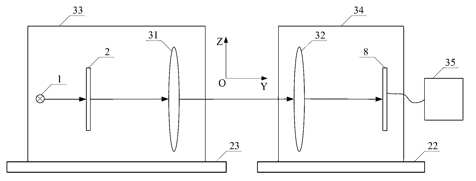
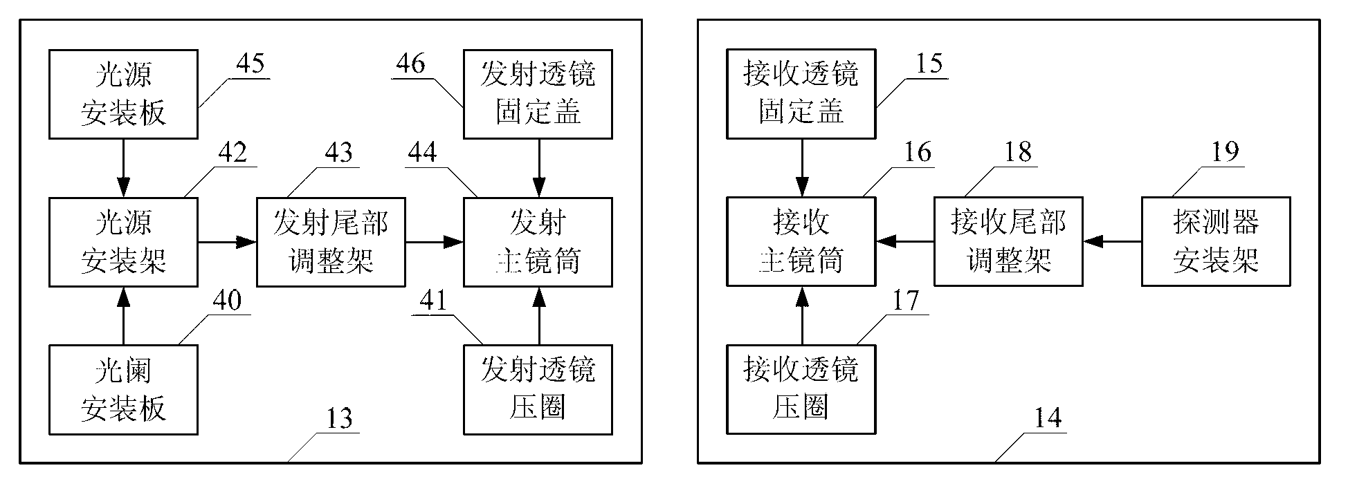
[0082] figure 2 It is the overall structure diagram of the installation device of the present invention. The mounting device proposed by the present invention is composed of a transmitting module mounting device 13 and a receiving module mounting device 14 . The light source 1, diaphragm 2 and emission optical system 31 of the three-dimensional optical deformation measuring device are installed inside the transmitting module installation device 13, and the receiving optical system 32 and the area array detector 8 of the three-dimensional optical deformation measuring device are installed inside the receiving module installation device 14 .

[0083] The transmitting module installation device 13 is composed of the transmitting main lens barrel 44 , the transmitting lens pressure ring 41 , the transmitting lens fixing cover 46 , the transmitting tail adjusting frame 43 , the light source mounting frame 42 , the light source mounting plate 45 and the aperture mounting plate 40 ...


PUM


Abstract

The invention discloses an installation device and method for an arc-second-level three-dimensional optical deformation measurement device and aims at conducting reliable installation on the arc-second level three-dimensional optical deformation measurement device. The installation device is formed by a transmitting module installation device and a receiving module installation device, the transmitting module installation device is composed of a transmitting main lens cone, a transmitting tail adjustment support, a light source installation support, a transmitting lens pressing ring, a transmitting lens fixing cover, a diaphragm installation plate and a light source installation plate, and the receiving module installation device is composed of a receiving main lens cone, a receiving lens pressing ring, a receiving lens fixing cover, a receiving tail adjustment support and a detector installation support. A sliding control and pressure fixing mode is adopted to install an adjustment portion of the three-dimensional optical deformation measurement device. By means of the installation device and method, the measurement device can be reliably installed, the installation device has the advantages of being adjustable in accuracy, convenient to adjust, stable and reliable after adjustment and the like, and the installation device has good stability under physical conditions of changed environment temperature, changed stress states and the like.

Description

technical field [0001] The invention belongs to the technical field of optical deformation measurement, and in particular relates to an installation device and method of an arc-second-level three-dimensional optical deformation measurement device. Background technique [0002] Optical deformation measurement technology can be widely used in large-scale motion platform deformation measurement and high-precision attitude reference transmission, etc. It has the advantages of high measurement accuracy, direct measurement, and good stability. Most of the current optical deformation measurement is realized by the collimated optical path method. In practical application, due to the influence of factors such as changes in environmental temperature and force state changes caused by the movement of the carrier, the final deformation measurement accuracy is closely related to the specific precision installation device and method. [0003] Hu Chunsheng of the National University of Def...

Claims


Application Information

Patent Timeline
IPC IPC(8): G01B11/16
Inventor 胡春生黄宗升秦石乔王省书高旸
Owner NAT UNIV OF DEFENSE TECH
Why Eureka
Try Eureka