A clamping method for transformer iron core iron yoke

A clamping method and transformer technology, which is applied in the manufacture of inductors/transformers/magnets, transformer/inductor magnetic cores, electrical components, etc., can solve problems such as excessive noise, fastening of bolts in place, and chip shifting, etc., to reduce noise and Loss, increased clamping force, and reduced deformation

Active Publication Date: 2015-11-18
BAODING TIANWEI GROUP TEBIAN ELECTRIC
View PDF6 Cites 0 Cited by
  • Summary
  • Abstract
  • Description
  • Claims
  • Application Information

AI Technical Summary

Problems solved by technology

After the iron core is erected, clamping clamps, clamping beams and other tools can achieve a certain clamping effect. Before erection, due to manpower cannot tighten all the bolts in place, and some iron core clamps are deformed, the integrity of the iron core cannot be guaranteed. The clamping force reaches the required pressure
After the iron core is erected, there are often quality problems such as large joints, shifting pieces, excessive noise, and excessive no-load, which seriously affect product quality and image, and also increase the time and production cost of repairing the iron core after erection

Method used


Image

  • A clamping method for transformer iron core iron yoke

Examples


Embodiment Construction

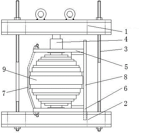
[0010] The present invention will be further described through the embodiments below in conjunction with the accompanying drawings.

[0011] A special tooling for clamping iron core yokes of transformers, including an upper clamping beam 1, a lower clamping beam 2, and a clamping screw 3, and the four corners of the upper clamping beam and the lower clamping beam are set to match each other. The four clamping screws respectively penetrate into the holes at the four corners, and are fastened by bolts to form a frame structure. The holes of the upper clamping beam and the lower clamping beam are oblong holes, which are used to adjust the gap between the clamping screws. The distance between the clamping screw and the end thread of the clamping screw is used to adjust the distance between the upper clamping beam and the lower clamping beam, which is suitable for iron cores of different diameters.

[0012] A method for clamping the iron core yoke of a transformer. The above-mentio...


PUM


Abstract

The invention relates to a clamping method for an iron core and an iron yoke of a transformer and dedicated tooling, and belongs to the technical field of transformer production. The technical scheme is that the dedicated tooling comprises an upper clamping beam (1), a lower clamping beam (2) and clamping screws (3). Holes which are mutually matched are arranged at four corners of the upper clamping beam and the lower clamping beam. The four clamping screws penetrate into the holes at the four corners respectively and fastened through bolts to form a frame structure. Holes of the upper clamping beam and the lower clamping beam are long round holes and are used for adjusting the distances among the clamping screws. Threads at ends of the clamping screws are used for adjusting the space between the upper clamping beam and the lower clamping beam and suitable for iron cores of different diameters. According to the clamping method for the iron core and the iron yoke of the transformer and dedicated tooling, clamp parts of the iron core and the iron yoke are clamped through the coordination of a hydraulic jack, and accordingly, the iron core clamping force is increased, laminated sheets are prevented from moving relative to the clamping parts during the rising of the iron core, and noise and losses of the transformer are reduced during the operation of the iron core. Internal distances of the clamping parts can be well controlled, the deformation of the clamping parts is reduced, the iron core clamping force is increased, the working efficiency is improved, and the manual operation burden is reduced.

Description

technical field [0001] The invention relates to a clamping method for a transformer iron core and iron yoke, which belongs to the technical field of transformer production. Background technique [0002] In the production of transformers, the clamping force of the transformer core must be guaranteed during the production process. If the clamping force of the core is not enough, it will easily cause core loss, noise and other effects, which is especially important in large-scale transformers. After the iron core is erected, clamping clamps, clamping beams and other tools can achieve a certain clamping effect. Before erection, due to manpower cannot tighten all the bolts in place, and some iron core clamps are deformed, the integrity of the iron core cannot be guaranteed. The clamping force reaches the desired pressure. After the iron core is erected, there are often quality problems such as large joints, shifting, excessive noise, and excessive no-load, which seriously affect...

Claims


Application Information

Patent Timeline
Patent Type & Authority Patents(China)
IPC IPC(8): H01F27/26H01F41/02
Inventor 赵峰张晟赵辉张江辉耿雪孙岩节
Owner BAODING TIANWEI GROUP TEBIAN ELECTRIC
Why Eureka
Try Eureka