Rope-driving multi-joint robot

A multi-joint robot, rope-driven technology, applied in the direction of manipulators, program-controlled manipulators, joints, etc., to achieve the effects of cost reduction, high transmission accuracy, and low cost

Inactive Publication Date: 2013-02-27
庄德胜
View PDF14 Cites 44 Cited by
  • Summary
  • Abstract
  • Description
  • Claims
  • Application Information

AI Technical Summary

Problems solved by technology

[0005] The purpose of the present invention is to provide a rope-driven multi-joint r

Method used


Image

  • Rope-driving multi-joint robot
  • Rope-driving multi-joint robot
  • Rope-driving multi-joint robot

Examples


Embodiment Construction

[0065] The present invention will be further described below in conjunction with the accompanying drawings and embodiments.

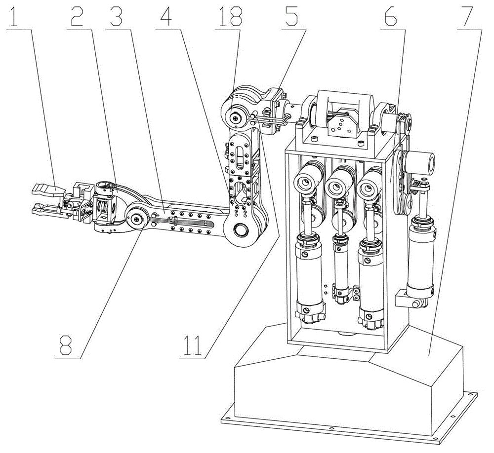
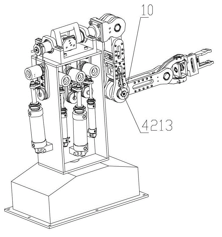
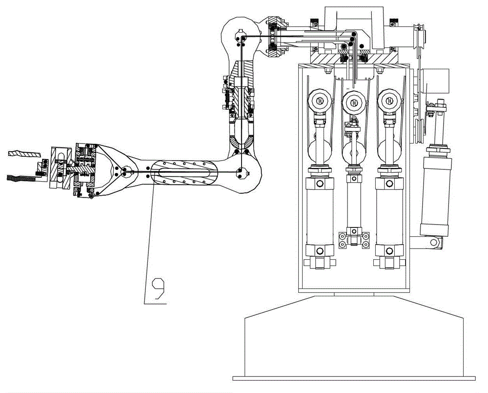
[0066] Such as Figure 1-2 As shown in 3, the rope-driven multi-joint robot of the present invention is divided into a hand 1, a wrist 2, a forearm 3, an upper arm 4, a shoulder 5, a waist 6 and a base 7. The waist 6 is arranged on the base 7, and the waist 6 passes through The crankshaft assembly 52 is connected to the shoulder 5, the shoulder 5 is connected to the upper arm 4 through the rotary joint shaft of the upper arm 4, and the upper arm is driven by the driven wheel assembly III18; the upper arm 4 is connected to the small arm 3 through the rotary joint shaft of the small arm 3, and the The driven wheel assembly II10 drives the forearm; the small arm 3 is connected to the wrist 2 through the rotating joint shaft of the wrist 2, and drives the wrist through the driven wheel assembly I8; the wrist 2 is connected to the hand 1 through the rotating...


PUM


Abstract

The invention belongs to the field of joint robots, and particularly relates to a rope-driving multi-joint robot which is used for solving the transmission and arrangement problems of a multi-joint steel wire rope. The rope-driving multi-joint robot comprises hands, wrists, forearms, upper arms, shoulders, a waist and a base, wherein the waist is arranged on the base and is connected with the shoulders through crankshaft assemblies, the shoulders are connected with the upper arms through rotary joint shafts, the upper arms are connected with the forearms through driven gear components II on the rotary joint shafts, the forearms are connected with the wrists through driven gear assemblies I on the rotary joint shafts, the wrists are connected with the hands through the rotary joint shafts, all the parts are connected with one another so as to form a plurality of joints, a rope-driving unit of the joints is connected with one or more than two of the waist, the shoulders, the upper arms, the forearms, the wrists and the hands through flexible ropes, so that the rope-driving multi-joint robot is formed. The robot has eight degrees of freedom in total, and can fully exert the advantages of steel wire rope transmission, such as high transmission precision, and easiness in distribution.

Description

technical field [0001] The invention belongs to the field of joint robots, in particular to a rope-driven multi-joint robot. Background technique [0002] The joints of the manipulator generally use a transmission mechanism in which the motor, gear reducer, and joint shaft are directly connected. This transmission mechanism requires the motor and the gear reducer to be installed at the attachment of the manipulator joint. The mechanism is simple but not compact, and the appearance is not clean. The particularly prominent disadvantage is that in a multi-joint manipulator, the transmission device such as the motor and gear reducer of the next-level joint becomes the load of the upper-level joint, which increases the requirements for the power and transmission components of the manipulator, thus causing the overall The increase in weight and internal consumption reduces the ability and efficiency of the mechanical arm to do work externally. [0003] Among the materials that ha...

Claims


Application Information

Patent Timeline
IPC IPC(8): B25J9/08B25J17/02B25J18/00
Inventor 庄德胜
Owner 庄德胜
Why Eureka
Try Eureka