Buffer for storing energy and assisting power for electric automobile

A technology for electric vehicles and buffers, applied to vehicle components, auxiliary drive devices, control devices, etc., can solve problems such as damage to electrical components, and achieve the effects of increasing mileage, increasing output power, and reducing temperature

Active Publication Date: 2014-02-12
HUAWEI TEHCHNOLOGIES CO LTD
View PDF6 Cites 0 Cited by
  • Summary
  • Abstract
  • Description
  • Claims
  • Application Information

AI Technical Summary

Problems solved by technology

[0005] The driving of electric vehicles depends on the coordinated work of various electrical components, but the instantaneous high current output during quick start will bring potential damage to electrical components

Method used


Image

  • Buffer for storing energy and assisting power for electric automobile
  • Buffer for storing energy and assisting power for electric automobile
  • Buffer for storing energy and assisting power for electric automobile

Examples


Embodiment 1

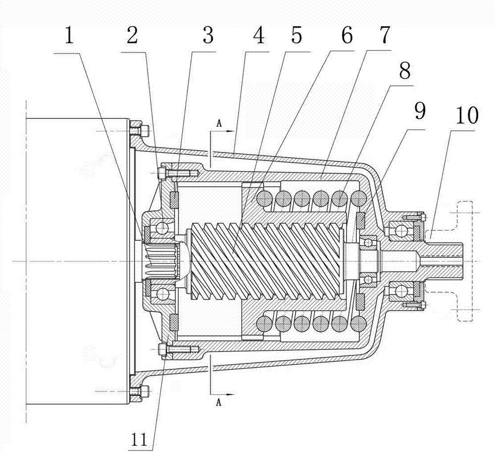
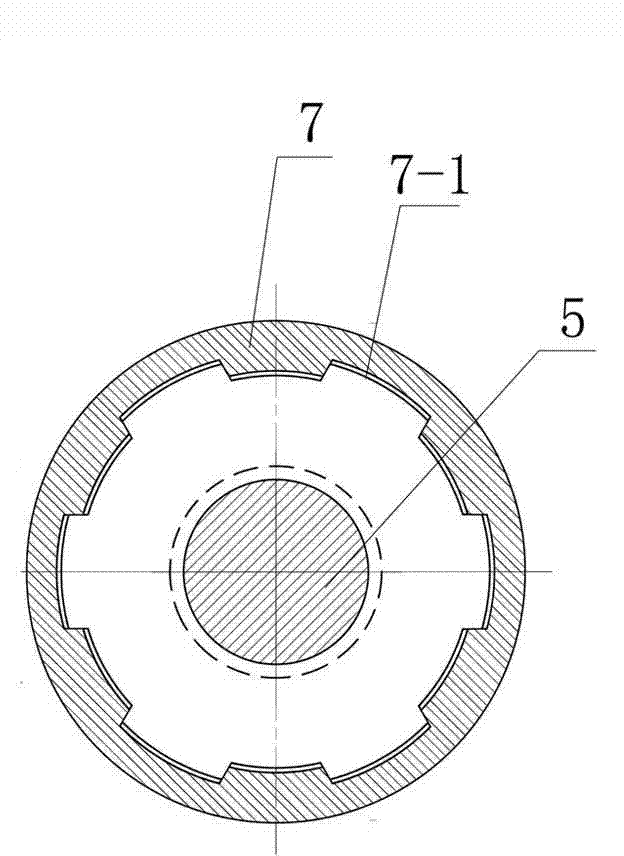
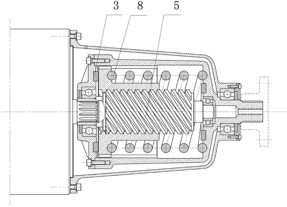
[0025] Such as figure 1 As shown, the energy accumulator described in this embodiment is mainly composed of a screw spindle 5 , a spline nut 6 , an energy storage spring 8 , an inner spline output bushing 7 , a casing 4 and an end cover 11 . The central inner hole of the spline nut 6 is connected with the outer helix of the screw main shaft 5, one end of the energy storage spring 8 is connected with the spline nut 6, and the other end is connected with the inner spline output sleeve 7, and the inner spline output shaft One end of the sleeve 7 is connected to the end cover 11, and the other end is connected to the terminal output shaft 10. The middle part of the inner spline output shaft sleeve 7 has a hollow cavity structure. In the hollow cavity of the output shaft sleeve. A single row centripetal thrust ball bearing 2 is arranged in the middle of the end cover 11, and an overload buffer rubber ring 9 is arranged on the inner end surface of the inner spline output shaft slee...

Embodiment 2

[0038] like Figure 4 As shown, the accumulator includes an overrunning clutch 12, a coil spring 13, a coil spring output sleeve 14 and a terminal output shaft 10, the coil spring 13 is wound on the coil spring output sleeve 14, and one end of the coil spring 13 is connected to the overrunning clutch active part 12-1 is connected, and the other end is connected with the coil spring output shaft sleeve 14; one end of the coil spring output shaft sleeve 14 is connected with the overrunning clutch follower 12-2, and the other end is connected with the terminal output shaft 10 through a spline.

[0039] The working principle and working process of the present embodiment are set forth below:

[0040] The overrunning clutch 12 is connected with the drive motor main shaft 1 . When the vehicle starts, because the starting resistance is very large and cannot be started synchronously at once, the sudden fast rotation of the drive motor main shaft 1 can only make the first rotation with...


PUM


Abstract

A method and a buffer for storing energy and assisting power for an electric automobile belong to the field of electric automobiles. The method and the buffer are characterized in that a spring is used for storing energy output by a driving motor spindle, and a middle transition shaft is arranged between the driving motor spindle and a terminal output shaft. During initial rotation of the driving motor spindle, under the effect of the middle transition shaft, the spring can be contracted and then releases energy, and the terminal output shaft rotates fast. The energy-storage spring is used for storing the initial rotation energy of a motor shaft, and when the energy stored in the spring and driving energy of a motor exceed resistance of the automobile, the energy storage spring releases energy so that output power can be greatly improved instantly, starting is fast, and no large current outputs. The service life of electric components is prolonged. Due to the fact that difference of power of the initially pressed spring and power of the spring pressed to the end is large, compression and releasing of the spring are sufficient to enable the transmission to be soft. Drivers feel comfortable and can feel soft acceleration and strong starting during a driving period.

Description

technical field [0001] The invention belongs to the field of electric vehicles, and in particular relates to an energy storage booster and buffer device for electric vehicles. Background technique [0002] With the continuous rise of crude oil prices and the needs of domestic environmental protection, new energy vehicles have become an industry that is supported and developed by the state. Over the years, electric vehicles have gradually been accepted by the people and promoted by the government. Since the on-board energy has not yet met people's requirements, but the research and development of electric vehicles is urgent, so various types of electric vehicles emerge in endlessly on the market. Since electric vehicles are not yet as perfect as gasoline vehicles, and there is no standard model, many types of so-called electric vehicles are still limited to sightseeing car structures, and their use is greatly limited. Current electric vehicles generally drive a reduction bo...

Claims


Application Information

Patent Timeline
Patent Type & Authority Patents(China)
IPC IPC(8): B60K25/02
Inventor 赵玉宝
Owner HUAWEI TEHCHNOLOGIES CO LTD
Why Eureka
Try Eureka