Fan control circuit

A fan control and circuit technology, applied in pump control, non-varactor pump, machine/engine, etc., can solve the problems of complex voltage conversion circuit structure, increased cost of mass production, waste of I/O resources, etc., to reduce Programming, saving I/O port, low price effect

Active Publication Date: 2015-01-14
SHENZHEN AMBITION ELECTRONICS
View PDF4 Cites 0 Cited by
  • Summary
  • Abstract
  • Description
  • Claims
  • Application Information

AI Technical Summary

Problems solved by technology

The defect of this control circuit is that it needs to occupy an independent I / O port, which not only wastes I / O resources, but also increases the amount of programming. increased cost

Method used


Image

  • Fan control circuit
  • Fan control circuit

Examples


Embodiment Construction

[0017] The present invention will be described in more detail below in conjunction with the accompanying drawings and embodiments.

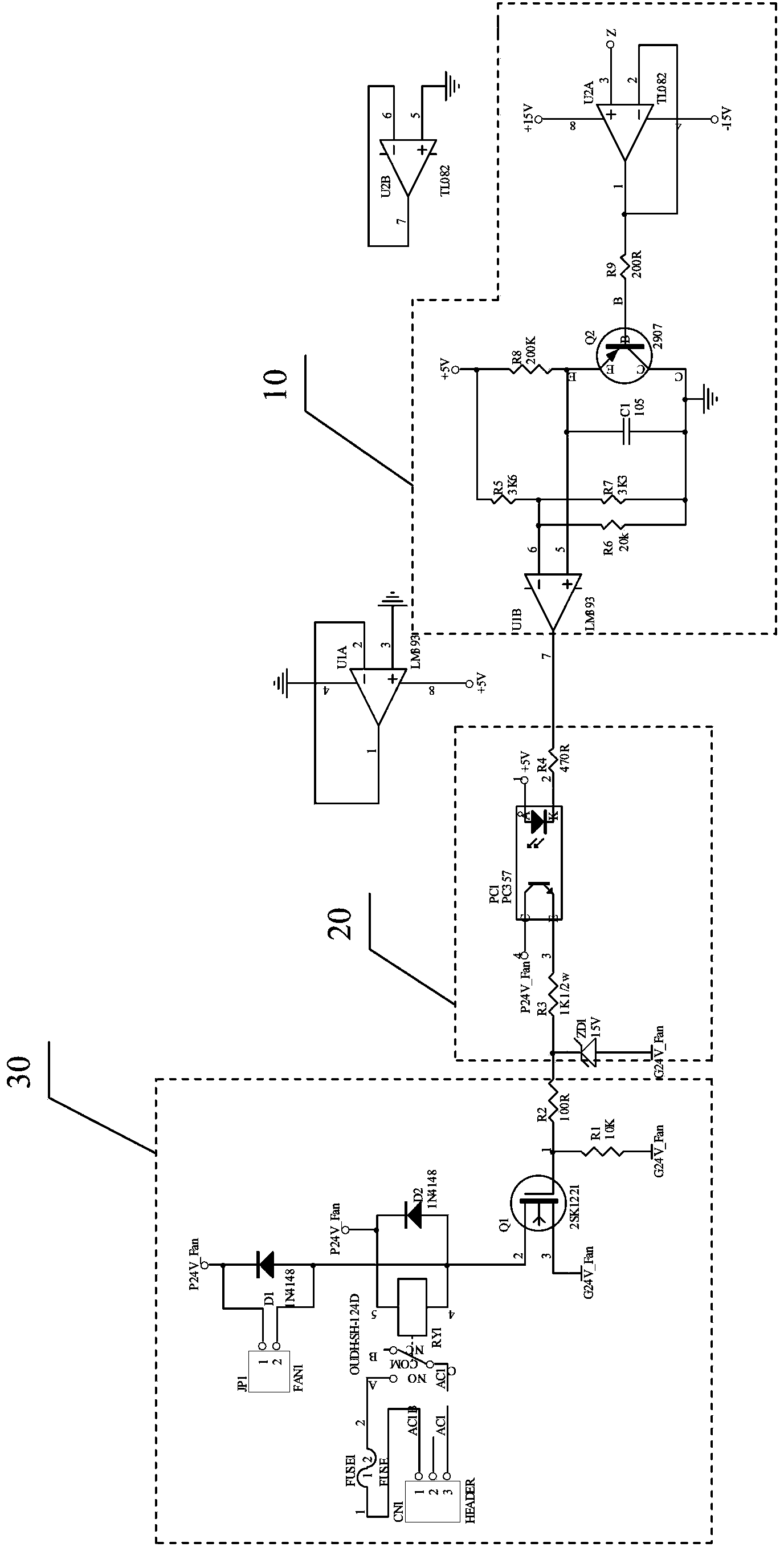
[0018] The invention discloses a fan control circuit, such as figure 1 As shown, it includes: a pulse processing unit 10, which is used to output a continuous DC voltage signal after voltage conversion of the input pulse width modulation signal; an isolated output unit 20, whose input terminal is connected to the pulse processing unit 10 The output terminal is used to isolate the input DC voltage signal and output it through the output terminal; a fan drive unit 30, the input terminal of which is connected to the output terminal of the isolated output unit 20, and is used to drive the fan motor to rotate or stop; The pulse processing unit 10 includes a voltage follower U2A, a PNP transistor Q2 and a voltage comparator U1B, the noninverting terminal of the voltage follower U2A is used for inputting a pulse width modulation signal, and its output t...


PUM


Abstract

The invention discloses a fan control circuit which comprises a pulse processing unit, an isolation output unit and a fan driving unit. The pulse processing unit is used for performing voltage conversion for input pulse width modulation signals and outputting continuous direct-current voltage signals. The input end of the isolation output unit is connected with the output end of the pulse processing unit, and the isolation output unit is used for isolating the input direct-current voltage signals and outputting the direct-current voltage signals through the output end. The input end of the fan driving unit is connected with the output end of the isolation output unit, and the fan driving unit is used for driving a fan motor to rotate or stop. The pulse width modulation signals in a circuit come from one path of multi-path pulse width modulation (PWM) pulse signals emitted out by a central processing unit (CPU) and can be shared with other circuits. Therefore, compared with the prior art, the fan control circuit omits an input / output (I / O) interface, reduces programming, is simple in structure, is formed by elements low in price, and reduces product cost.

Description

technical field [0001] The invention relates to the technical field of fan control, in particular to a fan control circuit. Background technique [0002] Since the inverter is equipped with power devices such as IGBTs, these power devices will generate a lot of heat during operation, which will increase the temperature of the inverter and affect the normal operation of the inverter. Therefore, a fan is usually installed to help it dissipate heat. In the existing fan control technology, a voltage conversion circuit is generally provided between the CPU and the fan, and the control signal output by the I / O port of the CPU is processed by the voltage conversion circuit to further control the rotation or stop of the fan. The disadvantage of this control circuit is that it needs to occupy an independent I / O port, which not only wastes I / O resources, but also increases the amount of programming. Increased costs. Contents of the invention [0003] The technical problem to be so...

Claims


Application Information

Patent Timeline
Patent Type & Authority Patents(China)
IPC IPC(8): F04D27/00
Inventor 陈鹏程
Owner SHENZHEN AMBITION ELECTRONICS
Why Eureka
Try Eureka