
Heat exchanger thermal-cold circle fatigue experiment device

A technology of fatigue test and cold and heat cycle, applied in the direction of measuring device, machine/structural component test, instrument, etc., can solve energy waste, energy waste and other problems

Inactive Publication Date: 2013-02-27
SOUTHEAST UNIV
View PDF4 Cites 2 Cited by
  • Summary
  • Abstract
  • Description
  • Claims
  • Application Information

AI Technical Summary

Problems solved by technology

[0003] The design scheme of the traditional heat exchanger cooling and heating cycle fatigue test device is to cool all the oil flowing out of the test piece first and then reheat it, which will obviously cause a lot of energy waste; the second is to set two cold and hot circuit, the return oil flowing out from the test piece enters the cold and hot oil tanks according to the temperature, so that part of the energy can be recovered
In the above scheme, the heating energy is not only used for the temperature change of the heat exchanger material itself, but also for the temperature change of the heat transfer oil medium, especially because of the cross-mixing of cold and heat, which will cause a large energy waste

Method used


Image

  • Heat exchanger thermal-cold circle fatigue experiment device

Examples


Embodiment Construction

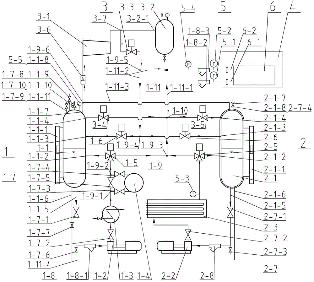
[0019] Examples see figure 1 ,

[0020] A heat exchanger cold and hot cycle fatigue test device, the cold and hot cycle fatigue test device includes a cold circuit 1, a hot circuit 2, a test piece cabinet 4, a control instrument group 5, and a test piece heat exchanger 6; the control instrument group 5 includes temperature sensor A5-1, temperature sensor B5-2, temperature sensor C5-3, pressure sensor 5-4 and pressure gauge 5-5; cold circuit 1 includes cold oil tank 1-1, cold oil pump 1-2, cooling Device 1-3, refrigerator 1-4, cold air three-way ball valve 1-5, cold air ball valve 1-6, cold valve group 1-7, cold filter group 1-8, cold three-way group 1-9, Four-way 1-10, connecting pipe group 1-11; cold valve group 1-7 includes valve A1-7-1, valve B1-7-2, valve C1-7-3, valve D1-7-4, valve E1 -7-5, valve F1-7-6, valve G1-7-7, valve H1-7-8, nitrogen supplement valve 1-7-9 and safety valve 1-7-10; cold filter group 1-8 Including filter A1-8-1, filter B1-8-2 and filter C1-8-3; co...


PUM


Abstract

The invention provides a heat exchanger thermal-cold circle fatigue experiment device with a gas displacement loop, which comprises a cold loop, a hot loop and the gas displacement loop, wherein the gas displacement loop comprises a compressor, a gas tank, a displacement pneumatic ball valve, an oil draining cold pneumatic ball valve, an oil draining hot pneumatic ball valve and the like; the inlet of the compressor is connected with an upper communication tube between a cold oil tank and a hot oil tank, one path of the outlet of the compressor is respectively connected with the gas tank and the displacement pneumatic ball valve through a tee, and the other path of the outlet of the compressor is connected with a tee of an outlet connecting tube of the heat exchanger serving as a test piece; and an inlet connecting tube of the heat exchanger serving as the test piece is respectively connected with the cold oil tank or the hot oil tank through a cross and the oil draining cold pneumatic ball valve or the oil draining hot pneumatic ball valve. The heat exchanger thermal-cold circle fatigue experiment device provided by the invention has the advantages that a gas displacement process is added between the alternate cooling and heating processes, and the remaining oil in the heat exchanger serving as the test piece is emptied to the corresponding cold oil tank or hot oil tank, thus preventing cold oil and hot oil from mixing. Compared with the traditional scheme, the device provided by the invention can save a large amount of electricity.

Description

technical field [0001] The invention relates to a heat exchanger cold and hot cycle fatigue test device. Background technique [0002] The heat exchanger cold and hot cycle fatigue test device usually uses heat transfer oil as the working medium, and alternately feeds cold and hot fluids into the heat exchanger of the test piece. If there is no leakage within the specified cycle, it is qualified. It is used to test the heat exchanger test piece. Alternating thermal fatigue strength of materials and welded parts. [0003] The design scheme of the traditional heat exchanger cooling and heating cycle fatigue test device is to cool all the oil flowing out of the test piece first and then reheat it, which will obviously cause a lot of energy waste; the second is to set two cold and hot circuit, the return oil flowing out from the test piece enters the cold and hot oil tanks according to the temperature difference, so that part of the energy can be recovered. In the above scheme...

Claims


Application Information

Patent Timeline
Patent Type & Authority Applications(China)
IPC IPC(8): G01M99/00G01M3/02
Inventor 陈亚平张治倪明龙陈世玉
Owner SOUTHEAST UNIV
Learn More