
Joint power-supply control system among detector power subsystems and control method thereof

A combined power supply and control system technology, applied to battery circuit devices, current collectors, electric vehicles, etc., can solve problems such as inability to fully utilize capacity, increase on-board load, waste of launch fuel, etc., to avoid high design capacity and optimize Whole star counterweight, easy to realize the effect of engineering

Inactive Publication Date: 2013-02-27
SHANGHAI INST OF SPACE POWER SOURCES
View PDF1 Cites 4 Cited by
  • Summary
  • Abstract
  • Description
  • Claims
  • Application Information

AI Technical Summary

Problems solved by technology

Some detectors may encounter the situation that they only need more power in a certain period of time, but less power in most of the time periods. If a battery with a large capacity is equipped at this time, its capacity cannot be fully utilized in most of the time periods, resulting in Waste, while increasing the load on the star, wasting launch fuel

Method used


Image

  • Joint power-supply control system among detector power subsystems and control method thereof
  • Joint power-supply control system among detector power subsystems and control method thereof
  • Joint power-supply control system among detector power subsystems and control method thereof

Examples


Embodiment Construction

[0032] Specific embodiments of the present invention will be further described below in conjunction with the accompanying drawings.

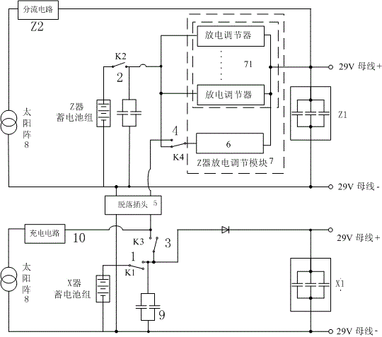
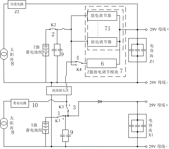
[0033] like figure 1 As shown, it is an embodiment of mutual power supply between the two devices of the joint power supply control system between the detector power supply subsystems of the present invention. In this embodiment, the two detectors used for deep space exploration and launched together are respectively: detector X and detector Z, detector X is a power supply detector, and detector Z is a power receiving detector.

[0034] Both the detector X and the detector Z are provided with a power supply and a power consumption circuit connected with the power supply. The power sources in both the detector X and the detector Z are composed of a solar array 8, a battery pack connected in parallel to the solar array 8, and a battery capacitor array 9.

[0035] The detector Z (power receiving detector) is also equipped with a Z device discharg...


PUM


Abstract

The invention discloses a joint power-supply control system for detector power subsystem. The joint power-supply control system comprises a backup discharge switch, a joint power-supply discharge regulator, a power-supplied detector discharge switch, a power-supply detector discharge switch and a double-device discharge switch, wherein the backup discharge switch is provided with a first connecting end, a second connecting end and a switching end, the switching end is connected between the first connecting end and the second connecting end in a switching way, and the switching end is connected with an electric circuit of a power-supplied detector through a circuit; the joint power-supply discharge regulator is connected between the switching end of the backup discharge switch and the electric circuit of the power-supplied detector through the circuit; both ends of the power-supplied detector discharge switch are respectively connected with a power supply of the power-supplied detector and the first connecting end of the backup discharge switch through circuits; the power-supply detector discharge switch is connected between the power supply of the power-supply detector and the electric circuit through the circuit; and one end of the double-device discharge switch is connected between the power-supply detector discharge switch and the electric circuit of the power-supply detector through the circuit, and the other end of the double-device discharge switch is connected with the second connecting end of the backup discharge switch through the circuit. The joint power-supply control system disclosed by the invention achieves the purpose that the short-time insufficient energy of a single detector can be supplied by other detectors jointly.

Description

technical field [0001] The invention relates to an aerospace power supply control technology, in particular to a combined power supply control system of a detector power supply subsystem and a control method thereof. Background technique [0002] In deep space exploration, considering issues such as launch costs and collaborative work, multiple probes are often launched together. Some detectors may encounter the situation that they only need more power in a certain period of time, but less power in most of the time periods. If a battery with a large capacity is equipped at this time, its capacity cannot be fully utilized in most of the time periods, resulting in Waste, increase the load on the star at the same time, waste launch fuel. If mutual power supply between the detectors can be realized, when a detector needs a large power, other non-working detectors can supply power to it, so that the rational utilization of energy can be achieved. Contents of the invention [...

Claims


Application Information

Patent Timeline
IPC IPC(8): H02J7/35
Inventor 金波刘勇许峰刘东陈达兴瞿诗霞
Owner SHANGHAI INST OF SPACE POWER SOURCES
Learn More