
Control device of automatic transmission for vehicle

A technology of automatic transmission and control device, which is applied in the direction of transmission control, clutch, elements with teeth, etc., can solve the problems that have not been proposed, the controllability is reduced, the engagement impact is increased, etc., to improve the fuel utilization rate, restrain the The effect of engaging shock and suppressing discomfort

Inactive Publication Date: 2015-04-08
TOYOTA JIDOSHA KK
View PDF7 Cites 1 Cited by
  • Summary
  • Abstract
  • Description
  • Claims
  • Application Information

AI Technical Summary

Problems solved by technology

However, unlike when the vehicle is started from a vehicle stop, re-acceleration is performed while the vehicle speed is gradually changing during deceleration running, so there is a possibility that the same control as when the vehicle is started cannot be smoothly performed.
For example, since the vehicle is running, there is a possibility that the sluggishness of the drive torque rise due to the clutch engagement response delay at the time of reacceleration becomes greater than the sluggishness of the drive torque rise at the time of vehicle startup.
Furthermore, when the clutch engagement is accelerated in order to suppress this sluggish feeling, there is a possibility that the engagement shock increases.
In this way, when the N control is started from running, although the improvement of fuel efficiency is realized, there is an increase in the discomfort caused by the change in deceleration, the sluggish feeling when re-accelerating, and the engagement shock when the N control is released. Possibility of large resulting in reduced handling
In addition, such a problem has not been publicly known, and a technique for starting N control while the vehicle is running while suppressing a decrease in drivability as much as possible has not yet been proposed.

Method used


Image

  • Control device of automatic transmission for vehicle
  • Control device of automatic transmission for vehicle
  • Control device of automatic transmission for vehicle

Examples


Embodiment

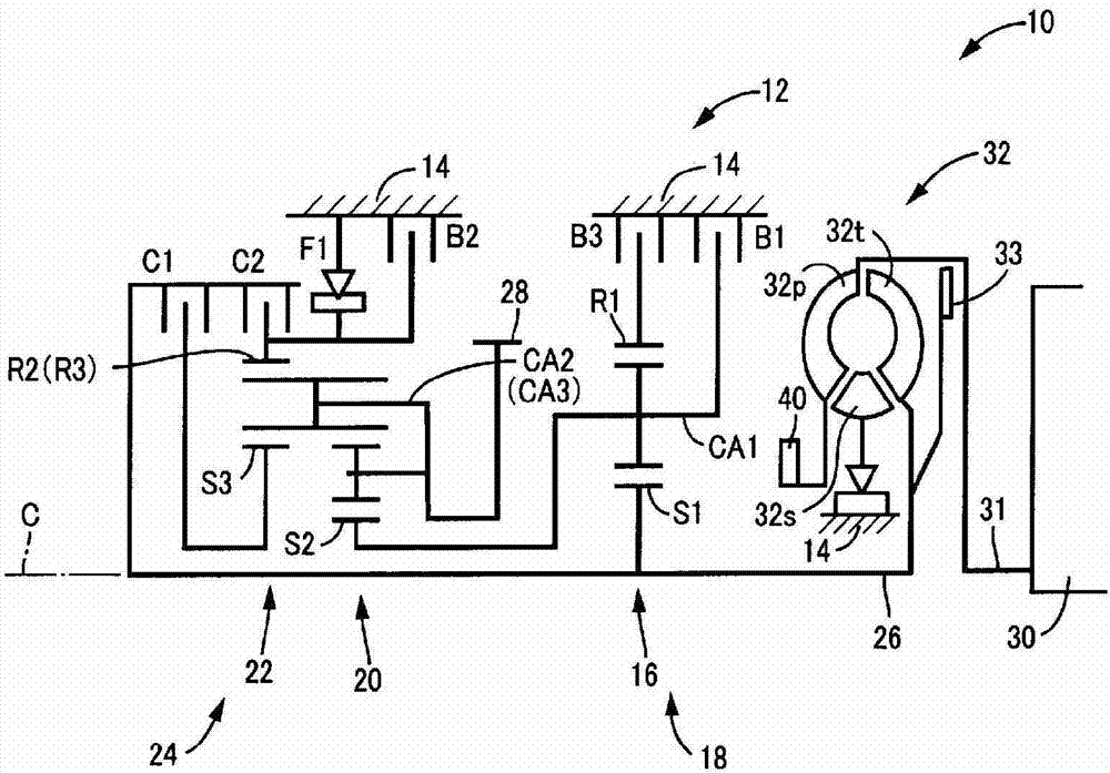
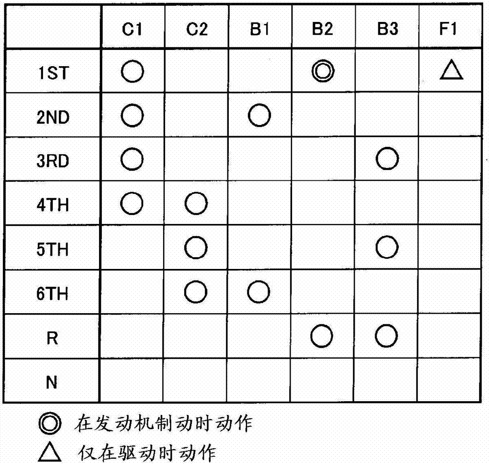
[0033] figure 1 It is a skeleton diagram illustrating the configuration of a vehicle automatic transmission 12 (hereinafter referred to as automatic transmission 12 ) included in a vehicle 10 to which the present invention is applied. figure 2 It is an operation table for explaining the operation state of the friction engagement device when a plurality of gear positions GS (gear stage GS) of the automatic transmission 12 are established. The automatic transmission 12 is suitably applied to an FF vehicle mounted in the left-right direction (horizontal) of the vehicle 10, and is installed in a transaxle case 14 (hereinafter referred to as the case 14 ) as a non-rotating member mounted on the vehicle body. On the axis C, there are the first transmission part 18 mainly composed of the first planetary gear device 16 of the single pinion type, the second planetary gear device 20 of the double pinion type, and the third planetary gear device of the single pinion type. The gear unit...


PUM


Abstract

Neutral control is carried out during vehicle driving while decline in drivability is suppressed. During deceleration driving when the accelerator is not pushed, a C1 clutch pressure is gradually reduced in a state where an automatic transmission (12) is left in a current gear stage (GSN) (phase 2 control), and if a starting gear ratio input rotational speed (NINS) during deceleration driving becomes equal to or less than a predetermined rotational speed (NEIDL+ß), the C1 clutch pressure is reduced such that a clutch (C1) is completely released in a state where the automatic transmission (12) is placed in a first gear stage (phase 4 control). For example, if a certain speed (V) is reached, output torque (TOUT) is gradually reduced according to the gradual reduction of the C1 clutch pressure so as to suppress the uncomfortable sensation caused by variation in deceleration speed. In addition, for example if the certain speed (V) is reached, the clutch (C1) is in a slipping state, and when the accelerator is pushed and N control during driving is thereby cancelled, a sensation of slowness upon re-acceleration can be suppressed while engagement shock is also suppressed.

Description

technical field [0001] The present invention relates to a control device for a vehicle automatic transmission that executes neutral control, and particularly relates to control when neutral control is executed while the vehicle is running. Background technique [0002] For example, a vehicle is known in which when the engine is idling, when the predetermined start conditions (for example, the shift position is in the "D" range for forward travel, the accelerator is not actuated, the brake is actuated, and the vehicle is in a stopped state) ) is established, in the state of keeping the "D" gear unchanged, make the transmission torque capacity (equivalent to the engagement torque, Engagement force, clutch pressure, etc.) is reduced, and the power transmission path from the engine to the drive wheels is in a state close to neutral (power transmission suppression state), so that the idling load of the engine can be suppressed and the fuel efficiency can be improved. gear contro...

Claims


Application Information

Patent Timeline
Patent Type & Authority Patents(China)
IPC IPC(8): F16H61/04F16D48/02
CPCF16D2048/0266F16D2500/70424F16H2061/0488F16D2500/3144F16H2061/207F16H61/0437F16D48/0206F16H2061/0496F16D48/06F16D2048/0233F16H2061/0481F16D2500/50293
Inventor 珍部友宏塚本典弘绫部笃志浅见友弘
Owner TOYOTA JIDOSHA KK
Learn More