
Electrowetting display driving system

An electrowetting display and display drive technology, applied to static indicators, instruments, etc., can solve the problems of lack of versatility

Active Publication Date: 2013-02-27
LIQUAVISTA BV
View PDF9 Cites 7 Cited by
  • Summary
  • Abstract
  • Description
  • Claims
  • Application Information

AI Technical Summary

Problems solved by technology

The disadvantage of the display drive system is the lack of versatility

Method used


Image

  • Electrowetting display driving system
  • Electrowetting display driving system
  • Electrowetting display driving system

Examples


Embodiment Construction

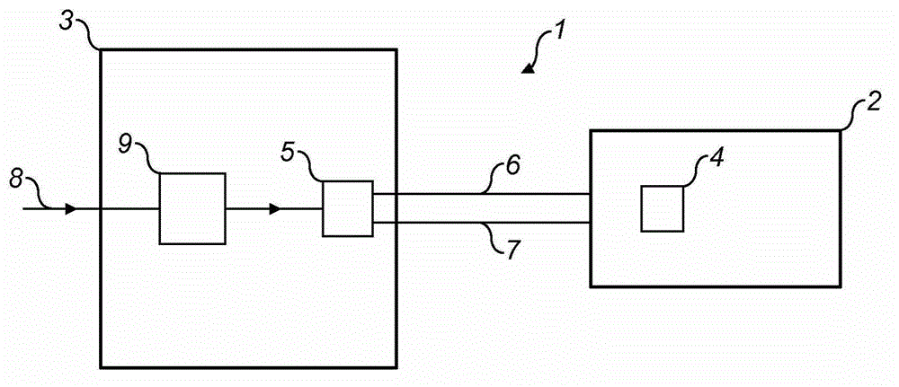
[0031] figure 1 A display device 1 including an electrowetting display device 2 and a display driving system 3 is schematically shown. The display device has at least one display element 4 . The driver stage 5 in the display driving system is connected to the display device via signal lines 6 and 7 . The driver stage outputs a display voltage in response to a data signal input to the display drive system via data signal line 8, the data signal being representative of the display state to be exhibited by the display device 2. When the display device includes a two-dimensional array of display elements (eg, an active matrix array), the data signal may be a TV signal, and the combined display state of the display elements forms an image. The display driving system may include a display controller 9 connected to the data signal lines 8 and providing signal levels and timings for controlling display elements. The driver stage 5 transforms the output of the display controller 9 i...


PUM


Abstract

This invention relates to a display driving system for an electrowetting display device having at least one display element, the display driving system comprising a driver stage for the display element, the driver stage providing a display voltage to be applied to the display element in response to a data signal representing an image to be displayed, the driver stage including a variable source providing a variable voltage in dependence on the data signal, the display driving system including an offset source providing an offset voltage, the display voltage being the sum of the offset voltage and the variable voltage.

Description

technical field [0001] The invention relates to an electrowetting display driving system and a method for driving an electrowetting display device. Background technique [0002] International patent application WO 2009 / 004042 discloses an electrowetting display device, wherein a display drive system controls the voltage applied to the display elements of the electrowetting display device. A disadvantage of display drive systems is the lack of versatility. [0003] It is an object of the present invention to provide a more general display driving system for electrowetting display devices. Contents of the invention [0004] According to the invention there is provided a display drive system for an electrowetting display device having at least one display element, the display drive system comprising a driver stage for the display element, the driver stage being responsive to a data signal representative of an image to be displayed , providing the display voltage to be appli...

Claims


Application Information

Patent Timeline
IPC IPC(8): G09G3/22G09G3/34
CPCG09G3/34G09G2330/021G09G2330/028G09G3/3433G09G2320/0626G09G3/348G09G2310/0289
Inventor 约·奥贝特亨利克斯·彼得罗妮拉·玛丽亚·德克斯
Owner LIQUAVISTA BV
Learn More