
Material belt transporting device

A transportation device and material belt technology, applied in the field of material belt transportation devices, can solve the problems of blocking workpiece transportation, affecting transportation quality, and small distance, and achieving the effect of preventing scratches

Inactive Publication Date: 2013-03-06
JIH VEI ELECTRONICS KUSN
View PDF6 Cites 0 Cited by
  • Summary
  • Abstract
  • Description
  • Claims
  • Application Information

AI Technical Summary

Problems solved by technology

However, affected by the existing technology, installation position, rotation speed, centrifugal force, etc., the two side plates often deflect axially during the rotation process. When the degree of deviation is too large, the two side plates will be in a certain position. The distance between the upper and lower plates is too small, which will hinder the transportation of workpieces, and the closeness of the side plates will cause the axial dimension of the roller to be unbalanced, which will affect the transportation quality

Method used


Image

  • Material belt transporting device
  • Material belt transporting device

Examples


Embodiment Construction

[0020] The present invention will be described in further detail below in conjunction with the accompanying drawings.

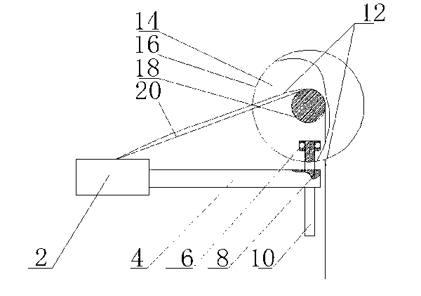
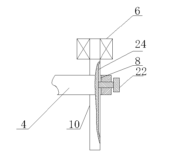
[0021] Such as figure 1 As shown, the strip conveying device of the present invention includes a workbench 2, an I-shaped wheel 14 and a material strip 12, the I-shaped wheel 14 includes two side plates 16, and a roller 18 sandwiched between the side plates 16, and the material strip 12 passes through The workbench 2 and the roller 18 are transported. In a preferred technical solution of the present invention, the material strip 12 is transported downward from the workbench 2 through the roller 18 and along the tangential direction of the roller 18. This mode of transportation is adopted , under the action of the friction force of the roller 18, the material strip 12 can be moved without applying any external force. In the process of transportation, the material strip 12 may be attached to the roller 18 and then be involved in the roller 18 because the tensi...


PUM


Abstract

The invention discloses a material belt transporting device, which comprises a work table, an I-shaped wheel and a material belt, wherein the I-shaped wheel comprises two side plates and a roller tube clamped between the side plates, the material belt is transported from the work table through the roller tube, the material belt transporting device also comprises a stop block, and the stop block is positioned between the two side plates. When the mode is adopted, the mutual approaching between the side plates can be prevented, the occurrence of the condition that the workpiece transportation is blocked when the mutual gap of the two side plates in a position is too small is avoided, and in addition, the generation of the adverse influence on the transportation quality caused by the axial size unbalance of the roller tube when the side plates mutually approaches can also be prevented.

Description

technical field [0001] The invention relates to a mechanical device, in particular a device for transporting material strips. Background technique [0002] The I-shaped wheel is a common transportation device. It includes two side plates and a roller sandwiched between the two side plates. The radial size of the roller is smaller than the radial size of the side plates. During transportation, the relative Compared with ordinary rollers, the two side plates of the I-shaped wheel can play a good role in limiting. However, affected by the existing technology, installation position, rotation speed, centrifugal force, etc., the two side plates often deflect axially during the rotation process. When the degree of deviation is too large, the two side plates will be in a certain position. If the distance between the upper and lower plates is too small, the transportation of the workpiece will be blocked, and the proximity of the side plates will cause the axial dimension of the rol...

Claims


Application Information

Patent Timeline
Patent Type & Authority Applications(China)
IPC IPC(8): B65H20/02B65H23/28B65H23/30
Inventor 郭土水江清源
Owner JIH VEI ELECTRONICS KUSN
Learn More