Solid-liquid buffer

A buffer and two-component technology, which is applied in the field of buffer mechanical devices, can solve the problems of difficulty in manufacturing process and installation, high cost, and large structural size of the buffer device, and achieve low machining requirements, small part size, and compact structure Effect

Active Publication Date: 2015-03-11
上海东泽环境科技股份有限公司
View PDF10 Cites 0 Cited by
  • Summary
  • Abstract
  • Description
  • Claims
  • Application Information

AI Technical Summary

Problems solved by technology

However, for the buffer device on the large-scale flood control gate of Suzhou Creek under design, if only a single buffer element mainly composed of springs is used, the structural size of the buffer device will be large, which not only makes the cost extremely high, but also brings down the manufacturing process. and implementation difficulty of installation

Method used


Image

  • Solid-liquid buffer
  • Solid-liquid buffer
  • Solid-liquid buffer

Examples


Embodiment Construction

[0034] The specific embodiments of the present invention will be described below in conjunction with the accompanying drawings.

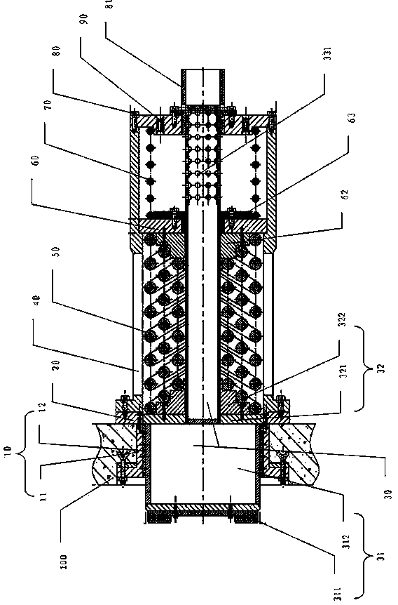
[0035] Such as figure 1 As shown, the solid-liquid dual-component buffer of the present invention is especially suitable for the buffering of the impact force between the river gate and the gate pier; the buffer uses springs and fluids as buffering components, wherein the buffering of the fluid and the liquid flow chamber is used. Design is the core invention of this buffer. For the convenience of the following statement, the impact contact end of the buffer is defined as the "front end", and the end away from the impact contact end is the "rear end".

[0036] The solid-liquid dual-component buffer is a cylindrical structure erected on the gate as a whole, and the main part of the buffer is a piston rod arranged in the cylindrical body. The piston rod is mounted on a hollow buffer main shaft 30 and can reciprocate axially in a cylindrical main sle...


PUM


Abstract

A solid-liquid buffer comprises an impact head, a combined spring and a volume-variable liquid flow chamber. After the impact head is impacted, the combined spring and the liquid flow chamber can absorb energy in a combined manner and particularly control flow of the liquid flow chamber linearly and mechanically, so that impact can be greatly alleviated. In order to enable the impact head to reset and circulate automatically after impact is ended, a reset spring arranged in the liquid flow chamber provides negative pressure. The solid-liquid buffer is simple and compact in structure, and small in part size, simple in manufacture process and convenient to mount and maintain under the condition that the impact is reduced. The solid-liquid buffer is a purely mechanical system, feasible, reliable and safe in action and particularly adaptive to underwater impact engineering.

Description

technical field [0001] The invention relates to a buffer mechanical device for reducing collision force, in particular to a working environment suitable for heavy load collisions. Background technique [0002] A sudden change in the speed of an object will produce an inertial force, which is numerically equal to the product of mass and acceleration. The greater the rate of change of the object's velocity or the greater the mass of the object, the greater the inertial force of the object. [0003] Collision is a physical phenomenon, and collision force is the external manifestation of the inertial force of objects. A simple example, assuming that two objects move on the same straight line, the front object moves slowly, and the rear object moves fast. When the two objects collide within a certain period of time, the moving speed of the two objects will change, and the collision force will be generated on the two sides. Between objects, this force is caused by the inertia of ...

Claims


Application Information

Patent Timeline
Patent Type & Authority Patents(China)
IPC IPC(8): E05F5/08E02B7/52
Inventor 瞿志豪
Owner 上海东泽环境科技股份有限公司
Why Eureka
Try Eureka