Heat exchanger

A heat exchanger and heat exchange tube technology, applied in the direction of heat exchanger shell, indirect heat exchanger, heat exchanger type, etc., can solve uneven secondary distribution, unavoidable heat exchange tube flow, open hole structure process complex issues

Active Publication Date: 2013-03-06
SANHUA HANGZHOU MICRO CHANNEL HEAT EXCHANGER
View PDF6 Cites 6 Cited by
  • Summary
  • Abstract
  • Description
  • Claims
  • Application Information

AI Technical Summary

Problems solved by technology

Even if the refrigerant flow rate through each hole is uniform, it cannot avoid the uneven flow rate in several adjacent heat exchange tubes
The refrigerant is distributed in waves among all the heat exchange tubes, making the secondary distribution uneven
In addition, the opening structure process is complex

Method used


Image

  • Heat exchanger
  • Heat exchanger
  • Heat exchanger

Examples


Embodiment Construction

[0082] The present invention will be further described below in conjunction with the drawings and specific embodiments.

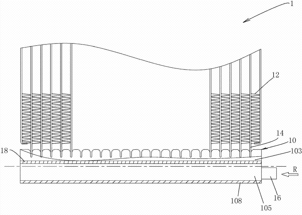
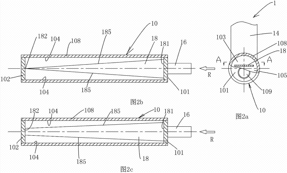
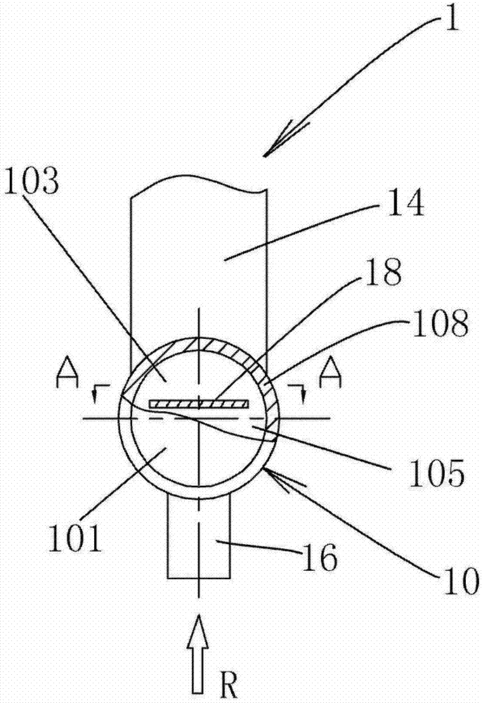
[0083] figure 1 Shows a heat exchanger according to an embodiment of the invention, Figure 2a Shows the heat exchanger with the connecting pipe arranged on the closure of the header, Figure 2b with 2c Two embodiments of the dispenser 18 are shown.

[0084] Reference Figure 1 to 2c , The heat exchanger 1 such as the microchannel heat exchanger according to the present invention includes: a header 10; a heat exchange tube 14, the end of the heat exchange tube 14 is connected to the tube wall 108 of the header 10 and the The heat exchange tube 14 is in fluid communication with the header 10; the fin 12 arranged between the heat exchange tubes 14; the connecting tube 16 connected to the header 10; the end caps 101 and 102 that close the ends of the header 10 The distributor 18 disposed inside the header 10, a gap is provided between the edge 185 of the distributo...


PUM


Abstract

The invention provides a heat exchanger, which comprises a collecting pipe and a distributor, wherein the distributor is arranged in the collecting pipe; and a clearance is formed between an edge in a longitudinal direction of the distributor and an inner wall of the collecting pipe. According to the distributor of the heat exchanger, refrigerating fluid can be distributed uniformly, and the process is simple.

Description

Technical field [0001] The invention relates to a heat exchanger, particularly a heat exchanger with a distributor. Background technique [0002] In traditional heat exchangers such as microchannel heat exchangers, when the refrigerant enters the header and is redistributed to the heat exchange tubes such as flat tubes, uneven distribution of the refrigerant will occur between the heat exchange tubes. . The heat exchange tube near the refrigerant inlet of the header and the heat exchange tube near the end of the header may have a larger refrigerant flow. In order to ensure that the refrigerant of the heat exchanger is evenly distributed in the heat exchange tubes, a metal draft tube is generally inserted into the collecting tube. The wall of the metal draft tube has multiple holes spaced along the length direction. The refrigerant can be distributed into the heat exchange tubes through these holes. [0003] The existing draft tube has a plurality of holes along the length direct...

Claims


Application Information

Patent Timeline
Patent Type & Authority Applications(China)
IPC IPC(8): F25B39/00F25B41/00
CPCF25B39/00F28F9/0282F25B41/00F28D2021/0068F28D1/05366
Inventor 董洪洲唐燕栋王艳红
Owner SANHUA HANGZHOU MICRO CHANNEL HEAT EXCHANGER
Why Eureka
Try Eureka