Interference detecting device based on synchronous carrier phase shift and detecting method of interference detecting device

A technology of interference detection and phase shifting, applied in the direction of measuring devices, optical devices, instruments, etc., can solve the problems of complex data processing, complex structure of interference detection devices, etc., achieve high light utilization rate, easy determination of carrier frequency, and improve measurement The effect of precision

Inactive Publication Date: 2013-03-06
HARBIN ENG UNIV
View PDF2 Cites 8 Cited by
  • Summary
  • Abstract
  • Description
  • Claims
  • Application Information

AI Technical Summary

Problems solved by technology

[0005] The present invention aims to solve the problem of complex structure of the existing synchronous carrier frequency phase shifting interference detection device and complex data processing of the detection method, and provides an interference detection device and detection method based on synchronous carrier frequency phase shifting

Method used


Image

  • Interference detecting device based on synchronous carrier phase shift and detecting method of interference detecting device
  • Interference detecting device based on synchronous carrier phase shift and detecting method of interference detecting device
  • Interference detecting device based on synchronous carrier phase shift and detecting method of interference detecting device

Examples


specific Embodiment approach 1

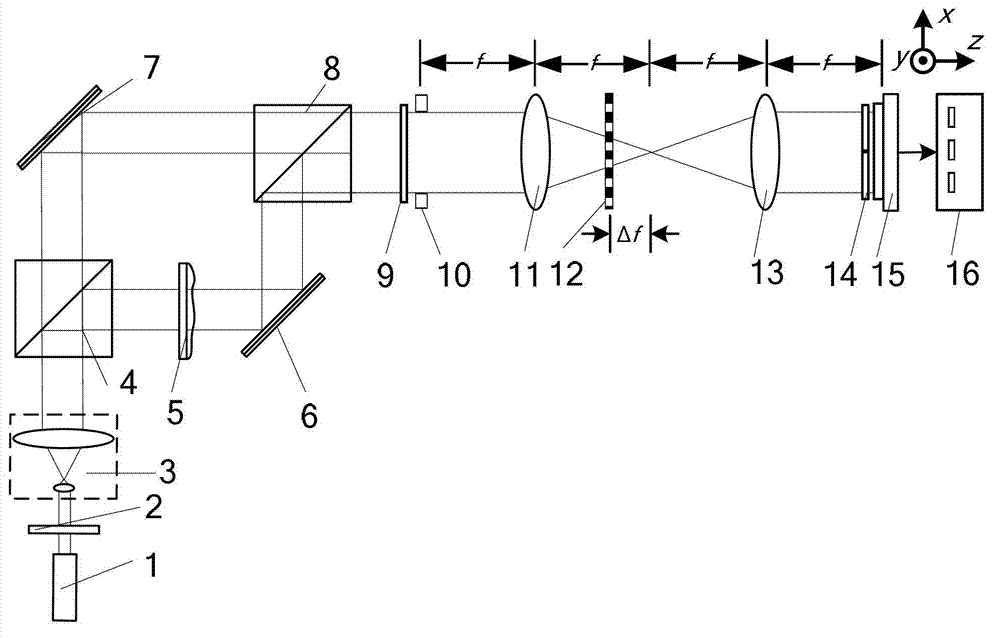
[0042] Specific implementation mode one: the following combination figure 1 Describe this embodiment, the interference detection device based on synchronous carrier frequency phase shifting described in this embodiment, it includes light source 1, it also includes polarizer 2, collimation beam expander system 3, first polarization beam splitter prism 4, object to be measured 5. The first reflector 6, the second reflector 7, the second polarization beam splitter prism 8, the λ / 4 wave plate 9, the rectangular window 10, the first Fourier lens 11, the one-dimensional periodic grating 12, the second Fourier Leaf lens 13, polarizer group 14, image sensor 15 and computer 16, wherein λ is the light wavelength of light beam emitted by light source 1,

[0043]The light beam emitted by the light source 1 enters the light receiving surface of the collimated beam expander system 3 through the polarizer 2, and the outgoing beam after collimated and expanded by the collimated beam expander ...

specific Embodiment approach 2

[0056] Embodiment 2: This embodiment is a further description of Embodiment 1. The one-dimensional periodic grating 12 is a binary one-dimensional periodic grating, a sine one-dimensional periodic grating or a cosine one-dimensional periodic grating.

specific Embodiment approach 3

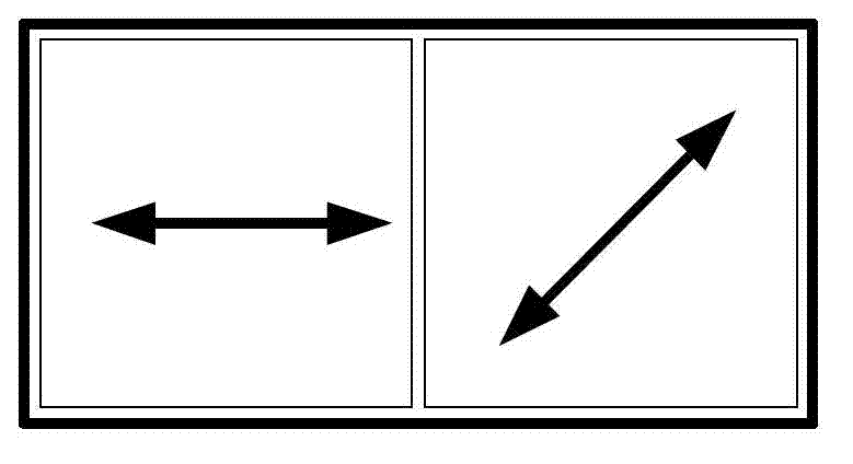
[0057] Specific implementation mode three: the following combination figure 1 with figure 2 Describe this embodiment mode, this embodiment mode is a further description of Embodiment 1 or 2, the polarizer group 14 is made up of two polarizers, and the two polarizers form a 1×2 array, and the light transmission axes of the two polarizers 0° and 45° to the x-axis, respectively.


PUM


Abstract

The invention relates to an interference detecting device based on synchronous carrier phase shift and a detecting method of the interference detecting device, which belong to the field of optical interference detection and solve the problems that the existing synchronous carrier phase shift interference detecting device is complex in structure and the existing detecting method is complex in data process. The interference detecting device comprises an optical source, a polarizing film, a collimation and beam expansion system, a first polarization splitting prism, an object to be detected, a first mirror, a second mirror, a second polarization splitting prism, a lambda/4 wave plate, a rectangular window, a first flourier lens, a one-dimensional period optical grating, a second flourier lens, a polarizing film set, an image sensor and a computer. The detecting method comprises the steps that light beams emitted by the light source are split into object light beams and reference light beams after passing through the first polarization splitting lens, two phase shift interference images are obtained through once exposure collection after a defocused grating splitting technique and a polarization modulating technique are combined, and phase retrieval of an object is achieved by eliminating a zero frequency component in a differential phase reduction method. The interference detecting device based on the synchronous carrier phase shift and the detecting method of the interference detecting device, disclosed by the invention, are suitable for shape measurement of small objects.

Description

technical field [0001] The invention relates to an interference detection device and detection method based on synchronous carrier frequency phase shifting, belonging to the field of optical interference detection. Background technique [0002] Carrier frequency interferometry uses object light and reference light with a certain angle to interfere, and the phase information of the object to be measured can be obtained from the formed single carrier frequency interferogram, which is suitable for real-time measurement of moving objects or dynamic processes. Method In order to reproduce the complex amplitude distribution of object light from a single interference pattern, it is necessary to tilt the object light and reference light to obtain a large enough angle to separate the zero-frequency component, real image and conjugate image of the interference pattern on the spectrum plane, so , cannot make full use of the lateral resolution or spatial bandwidth product of the image s...

Claims


Application Information

Patent Timeline
Patent Type & Authority Applications(China)
IPC IPC(8): G01B9/02
Inventor 钟志单明广郝本功窦峥张雅彬刁鸣
Owner HARBIN ENG UNIV
Why Eureka
Try Eureka