Pressure sensor and pressure sensing method

A sensing method and pressure sensing technology, applied in fluid pressure measurement involving magnet displacement, etc., can solve problems such as ignition, damage, and low accuracy

Inactive Publication Date: 2013-03-06
GRAND MATE
View PDF5 Cites 18 Cited by
  • Summary
  • Abstract
  • Description
  • Claims
  • Application Information

AI Technical Summary

Problems solved by technology

[0007] However, although the above-mentioned piezoelectric pressure sensing device can improve the shortcomings of known pressure sensing devices such as low accuracy and susceptibility to temperature, the piezoelectric pressure sensing device directly applies pressure to the piezoelectric pressure source through a pressure source. material, after a period of use, the piezoelectric pressure sensing device is prone to rust, moisture or d

Method used


Image

  • Pressure sensor and pressure sensing method
  • Pressure sensor and pressure sensing method
  • Pressure sensor and pressure sensing method

Examples


Embodiment Construction

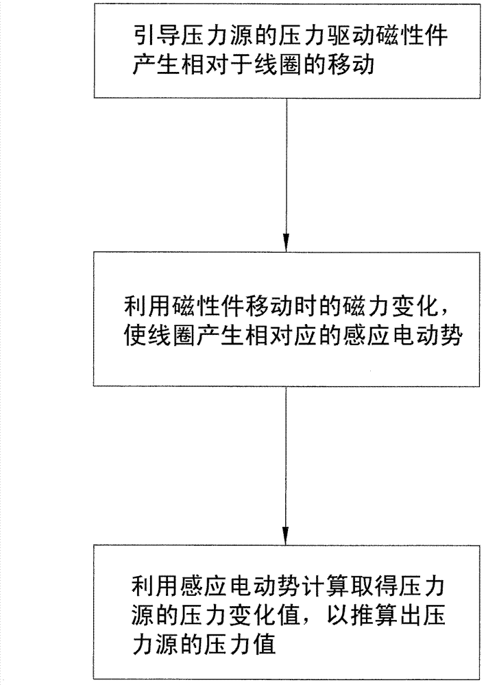
[0046] The pressure sensing method provided by the present invention is used to sense the pressure of a pressure source, and the method includes the following steps:

[0047] A) directing the pressure of the pressure source to drive a magnetic member for generating a magnetic force close to or away from a coil of conductive material;

[0048] B) Using the change of magnetic force when the magnetic part moves, the coil generates corresponding induced electromotive force.

[0049] C) Using the induced electromotive force to calculate the pressure change value of the pressure source, so as to calculate the pressure value of the pressure source.

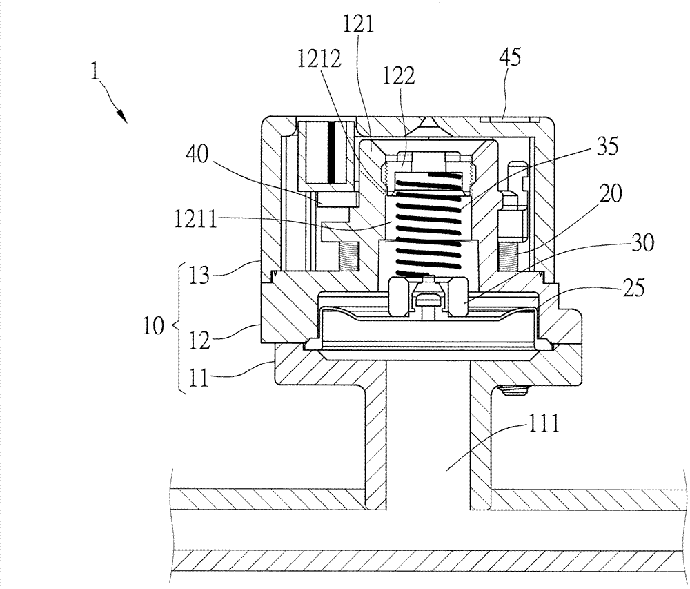
[0050]According to the above method, the present invention provides a pressure sensing device, which includes a housing, a coil, a stretchable film layer, and a magnetic element. Wherein, the casing has a detection hole, and one end of the detection hole is used to contact the pressure source; the coil is made of conductive material and...


PUM


Abstract

A pressure sensing method is used for sensing pressure of a pressure source, and includes the steps: guiding the pressure of the pressure source to drive a magnetic piece for generating magnetic force to be close to or away from a coil made of conducting materials, then, enabling the coil to generate corresponding induction electromotive force by the aid of magnetic force changes during moving of the magnetic piece, and finally, utilizing the induction electromotive force to obtain a pressure change value of the pressure force by means of computing. In addition, the invention further discloses a pressure sensor using the method to achieve pressure sensing.

Description

technical field [0001] The present invention is related to a sensing device, and more specifically refers to a pressure sensing device and a sensing method thereof. Background technique [0002] Generally speaking, the industry usually uses pressure sensing devices such as U-tube manometers or Bourdon-tube gages to measure pressures such as tire pressure, air pressure, and water pressure. [0003] The above-mentioned U-shaped tube pressure gauge usually uses water or mercury as the standard liquid in the tube; when the two ends of the U-shaped tube are not pressurized, the liquid levels of the two tubes are on the same level. If there is a pressure difference between the two ends, there will be a difference in the height of the liquid column between the two tubes. The height difference of the liquid column can properly represent the pressure difference between the two ends of the U-shaped tube to measure the pressure of the pressure source. [0004] see also figure 1 The B...

Claims


Application Information

Patent Timeline
IPC IPC(8): G01L9/14
Inventor 黄重景黄锦颖黄信铭黄信雄林冠州叶严仁赖锵文
Owner GRAND MATE
Why Eureka
Try Eureka