

SAR (synthetic aperture radar) direction ambiguity suppression method based on antenna main lobe dominance intensity constraint
An antenna main lobe and azimuth ambiguity technology, which is applied in radio wave reflection/re-radiation, radio wave measurement system, utilization of re-radiation, etc., can solve problems such as interference, affecting SAR image quality, and increasing difficulty of system optimization design. Suppresses the effect of azimuth blurring
- Summary
- Abstract
- Description
- Claims
- Application Information
AI Technical Summary
Problems solved by technology
Method used
Image

Examples
Embodiment Construction
[0023] In order to more clearly illustrate the technical solutions and technical advantages of the present invention, the present invention will be further described in detail below in conjunction with specific embodiments and with reference to the accompanying drawings.
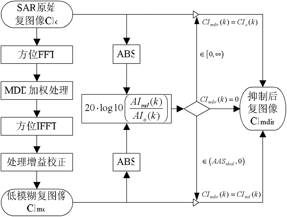
[0024] A SAR image azimuth ambiguity suppression method based on the antenna main lobe dominant strength constraint of the present invention, the complete processing flow is as follows figure 1 shown. The concrete steps of described method comprise:
[0025] 1) Determine the dominant area of the main lobe energy of the antenna
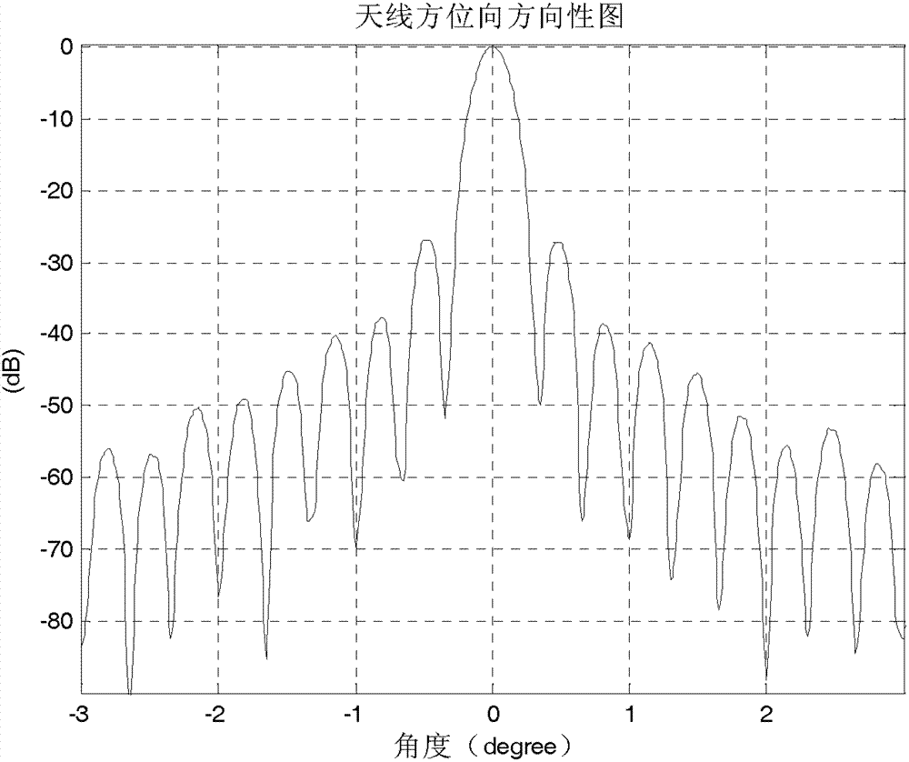
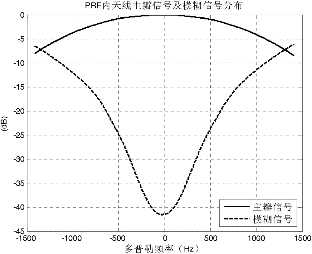
[0026] According to the energy distribution of the main lobe and side lobe of the antenna (such as figure 2 shown), determine the dominant area of the main lobe of the antenna within the PRF range, that is, first search for the fuzzy-Doppler curve (such as image 3 As shown, the abscissa: ±PRF / 2; the ordinate: the pole of the blur amplitude), and then, using this pole as the ...
PUM
 Abstract
Description
Claims
Application Information