Touch panel and touch display device

A touch display device, touch panel technology, applied in the direction of instruments, electrical digital data processing, data processing input/output process, etc., can solve the problems of affecting signal line signal transmission, reducing the flexibility of touch panel, etc., to achieve Improve flexibility and maintain texture

Inactive Publication Date: 2013-03-06
WINTEK CHINA TECH LTD +1
View PDF3 Cites 9 Cited by
  • Summary
  • Abstract
  • Description
  • Claims
  • Application Information

AI Technical Summary

Problems solved by technology

However, even if the insulating layer 150 is provided on the metal logo pattern 140, since the logo pattern 140 protrudes from the surface of the surrounding light-shielding layer 130, the insulating layer 150 sandwiched between the logo pattern 140 and the transmission lines 124a, 124b will be affected by the thickness. Insufficient and produce serious capacitive effect, even affect the signal transmission of the signal line, so, Figure 1A The transmission lines 124a and 124b shown by dotted lines in the figure need to adopt the layout method of winding design, thus reducing the flexibility of the touch panel in line layout and production.

Method used


Image

  • Touch panel and touch display device
  • Touch panel and touch display device
  • Touch panel and touch display device

Examples


no. 1 example

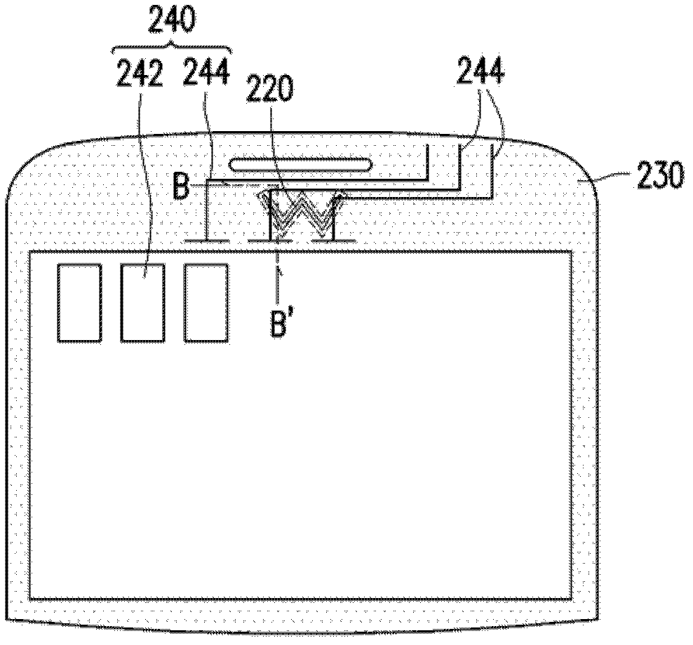
[0043] Please refer to Figure 2A and Figure 2B , Figure 2B for Figure 2A Sectional view along section line BB'. The touch panel 200 includes a substrate 210 , a logo pattern 220 , a decoration layer 230 and a touch element 240 . The touch element 240 is located on the substrate 210 . The touch element 240 of this embodiment includes at least one touch unit 242 and at least one transmission line 244 electrically connected to the touch unit 242 . The logo pattern 220 is located at a predetermined position of the substrate 210 , and the designer can use the logo pattern 220 to present a brand logo (logo), button icon (Icon) or any desired graphics on this area. The decoration layer 230 is located on the surface periphery of the substrate 210 .

[0044] The decoration layer 230 of this embodiment coats the logo pattern 220 on the substrate 210 , thus avoiding the problem that the logo pattern 220 is oxidized due to direct exposure to the outside, resulting in a color cha...

no. 2 example

[0052] Please refer to Figure 5 , the touch panel 300 of this embodiment is similar to the touch panel 200 of the first embodiment, and the same components are denoted by the same symbols. Only the touch panel 300 of this embodiment has more components of the color matching layer 310 than the touch panel 200 of the first embodiment

[0053] In order to further increase the special visual changes of the logo pattern 220 to create an excellent visual effect, a color-matching layer 310 can be added on the logo pattern 220. The material of the color-matching layer 310 can be photoresist of different colors depending on the product design or color matching requirements. , ceramics, inks or other materials such as diamond-like carbon, such as red filter photoresist, blue filter photoresist or green filter photoresist that can form a color filter layer. The color of the color matching layer 310 is different from the color of the decoration layer 230 , so that the overall logo patte...


PUM


Abstract

The invention relates to a touch panel which comprises a substrate, a logo, a decorative layer and a touch element. The logo is positioned on the substrate and between the substrate and the decorative layer, the decorative layer is positioned at the peripheral edge of the surface of the substrate, and the touch element is positioned on the substrate. Flexibility of the touch panel in terms of wiring and manufacturing can be improved, and the sense of design of the touch panel is improved. The invention further provides a touch display device with the touch panel.

Description

technical field [0001] The invention relates to a touch panel, in particular to a touch panel with a decorative layer on a logo pattern and a manufacturing method thereof. Background technique [0002] Please refer to Figure 1A , the touch panel 100 has a touch element 120, a light-shielding layer 130 and a logo (LOGO) pattern 140, and the touch element 120 includes a sensing electrode 122 and a transmission line 124, and the light-shielding layer 130 is used to shield the transmission line 124 to prevent the user from using The transmission line 124 is seen from time to time. [0003] Please refer to Figure 1B In the conventional touch panel 100, the opening H is firstly made by using the underlying light-shielding layer 130 to serve as the preset position of the logo pattern. Next, the metal logo pattern 140 is plated on the predetermined position of the logo pattern 140 . However, the logo pattern 140 produced by such a production method is exposed due to lack of pro...

Claims


Application Information

Patent Timeline
Patent Type & Authority Applications(China)
IPC IPC(8): G06F3/041
Inventor 许福明邓志容苏国彰枋志尧
Owner WINTEK CHINA TECH LTD
Why Eureka
Try Eureka