Electronic module, light emitting device and manufacture method of electronic module

A technology for electronic modules and molds, applied in circuit thermal devices, printed circuit manufacturing, circuits, etc., can solve the problems of damage to lighting devices, low stability of electronic modules, and high thermal resistance.

Inactive Publication Date: 2013-03-06
OSRAM GMBH
View PDF5 Cites 2 Cited by
  • Summary
  • Abstract
  • Description
  • Claims
  • Application Information

AI Technical Summary

Problems solved by technology

However, since the encapsulation material 4 has a relatively large thickness and high sealing performance, it is not convenient to export the heat generated by the heat source 1, such as the LED, to the ou

Method used


Image

  • Electronic module, light emitting device and manufacture method of electronic module
  • Electronic module, light emitting device and manufacture method of electronic module
  • Electronic module, light emitting device and manufacture method of electronic module

Examples


Embodiment Construction

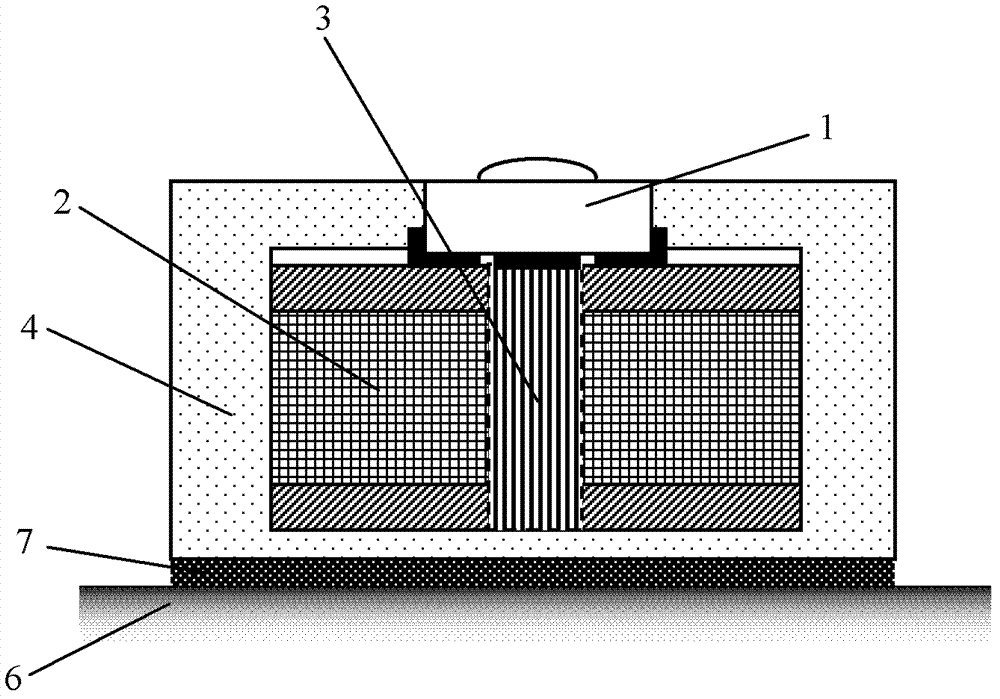
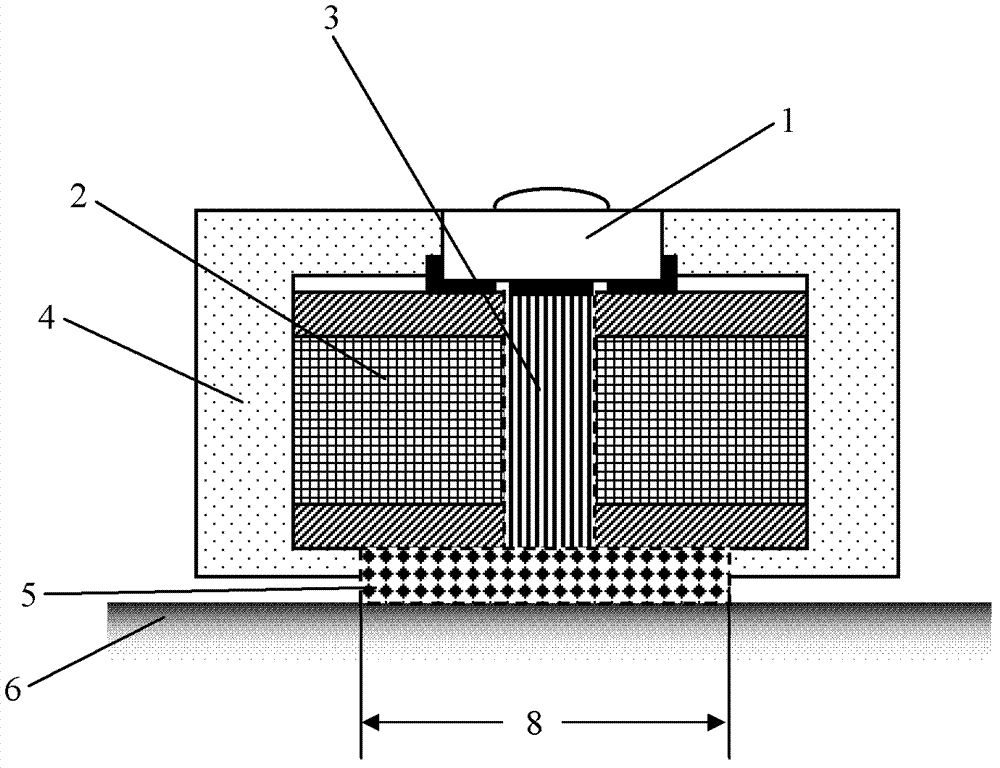
[0036] figure 2 A cross-sectional view of an electronic module according to the invention is shown. The circuit board 2 on which the heat source 1, such as an LED, is mounted can be, for example, an FR4 printed circuit board, which is a double-layer circuit board and has low thermal conductivity similar to conventional plastics, with a thermal conductivity of about 0.2W / m*K . A through thermal hole 3 is formed on the circuit board 2 , and the heat source 1 is located directly above the thermal hole 3 and is in direct thermal contact with it, so that the heat emitted by the heat source 1 can be guided to the outside of the circuit board 2 through the thermal hole 3 . In order to obtain a good heat conduction effect, the thermal hole 3 is usually filled with a heat conduction medium. The encapsulation material 4 for encapsulating the circuit board 2 is usually a hard plastic, and its thermal resistance can be equivalent to that produced by a material with a thermal conductivi...


PUM

PropertyMeasurementUnit
Thicknessaaaaaaaaaa

Abstract

The invention relates to an electronic module used for being installed to a mounting surface (6). The electronic module comprises a circuit board (2) disposed on a heat source (1) and envelope material (4) which packages the circuit board (2) at least from the other side facing to the heat source (1). The circuit board (2) is provided with a through heat hole (3). The heat source (1) thermally contacts with the heat hole (3). At least part of the other side of the circuit board (2), corresponding to the heat hole (3), is provided with a cavity (8), and the cavity (8) is filled with heat conduction material (5) which is thermally conductively connected to the mounting surface. In addition, the invention further relates to a light emitting device, and a manufacture method of the electronic module. The electronic module is simple in structure and low in manufacture cost. The envelope material of the module is modified, so that the electronic module is low in thermal resistance and fine in stability.

Description

technical field [0001] The invention relates to an electronic module, a light emitting device and a manufacturing method of the electronic module. Background technique [0002] Today, lighting devices are increasingly used in daily life, and most of the electronic modules of these lighting devices have plastic encapsulation materials, which usually appear in the form of an external housing. This encapsulation material ensures that the electronic module meets the requirements of dust and water resistance in industrial use, and also avoids damage to the circuit board and the electronic components mounted on it, especially LEDs, during transportation or installation. [0003] as in figure 1 As shown in , the encapsulation material 4 integrally seals the heat source 1 , such as the circuit board 2 with LEDs therein, and a thermal hole 3 passing through the circuit board 2 is provided under the heat source 1 . Such a fully sealed electronic module can be fixed on the mounting s...

Claims


Application Information

Patent Timeline
IPC IPC(8): H01L33/48H01L33/64H01L33/00
CPCH05K2201/10106H05K2203/1327H05K3/284H05K2203/1316H05K1/0206H05K3/0061Y10T29/49146H05K2203/10H05K2203/1147
Inventor 李皓陈小棉冯耀军陈鹏
Owner OSRAM GMBH
Why Eureka
Try Eureka