Electric power converter control device and electric power conversion control method

A technology of power converter and control device, applied in AC motor control, output power conversion device, control system, etc., can solve the problems of motor output torque ripple, etc. Effect

Active Publication Date: 2015-04-22
HITACHI IND PROD LTD
View PDF6 Cites 0 Cited by
  • Summary
  • Abstract
  • Description
  • Claims
  • Application Information

AI Technical Summary

Problems solved by technology

[0018] Also, in the method of synchronously changing the carrier wave and the voltage command value at the same timing described in Patent Document 2, in PWM control in a 5-level inverter like the present invention, the phase difference Φ of the two carriers is due to It changes according to the frequency of the carrier wave, so even if the above method is used, the above phase difference cannot be maintained at the specified value, and the output torque ripple of the motor caused by the output voltage error will occur.

Method used


Image

  • Electric power converter control device and electric power conversion control method
  • Electric power converter control device and electric power conversion control method
  • Electric power converter control device and electric power conversion control method

Examples


Embodiment 1

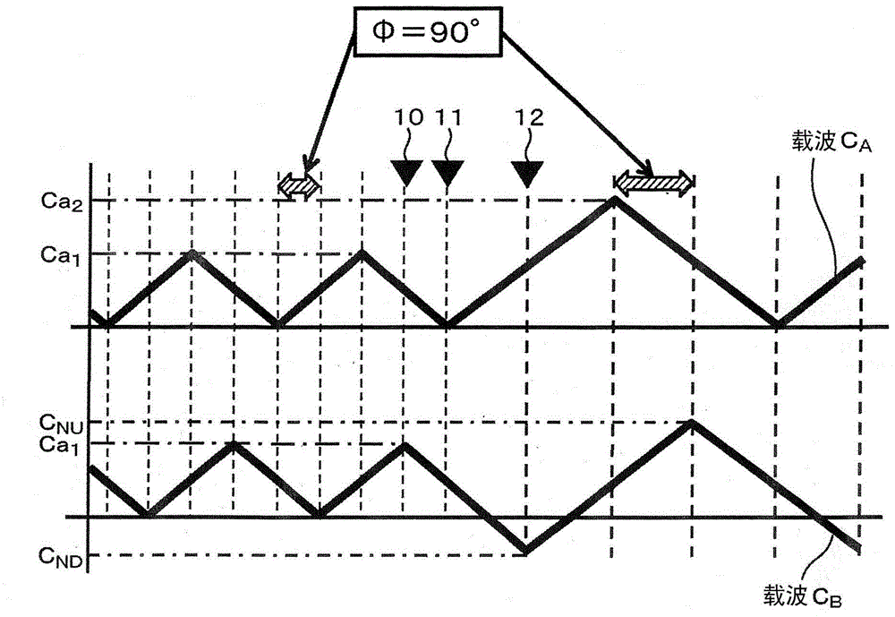
[0075] figure 1 Shows the first embodiment of the present invention. figure 1 It represents a 5-level power conversion device in which N=2, M=2, L=4 and the single-phase power converter is set as a single-phase 3-level power converter ( Figure 11 ), the above carrier C A 、C B diagram of the waveform. For the above carrier C A , at such that the above carrier frequency f c value from f c1 change to f c2 case, the upper side peak from Ca 1 Change to Ca 2 . The lower peak regardless of the carrier frequency f c How to always be sure.

[0076] On the other hand, for the above carrier C B , at such that the above carrier frequency f c value from f c1 change to f c2 In the case of ND , the upper peak C NU .

[0077] C ND =(Ca 1 -Ca 2 ) / twenty two)

[0078] C NU =(Ca 1 +Ca 2 ) / twenty three)

[0079] Regarding the above carrier C A 、C B The change timing of the upper peak value and the lower peak value of the B Change the above-mentioned carrier C befor...

Embodiment 2

[0084] Next, the points different from the first embodiment will be described with respect to the second embodiment of the present invention. In Embodiment 1, regardless of the carrier frequency f c Carrier C A The lower peak value is always set to a certain value, but if Figure 5 As shown, it is also possible to place the carrier C A The upper peak value of is always set constant.

[0085] If as in this embodiment for the above carrier C A And if the upper peak value is set constant, then when the frequency f of the above-mentioned carrier c value from f c1 change to f c2 case, move the lower side peak from -Ca 1 Change to -Ca 2 .

[0086] On the other hand, for the above carrier C B , at such that the above carrier frequency f c value from f c1 change to f c2 In the case of , as shown in the following equations (4) and (5), the upper peak C NU , lower peak C ND .

[0087] C NU =(Ca 2 -Ca 1 ) / twenty four)

[0088] C ND =-(Ca 1 +Ca 2 ) / 2...(5)

[0089]...

Embodiment 3

[0094] Next, a third embodiment of the present invention will be described on points different from the first embodiment. Although in Embodiment 1 regardless of the carrier frequency f c Carrier C A When the lower peak value is always set to a certain time, individually change the above carrier C A The upper peak of the above carrier C B The upper peak, the lower peak, but if Figure 7 As shown, the above carrier C can also be A 、C B The upper peak value and lower peak value are always set constant, and at the frequency f c When there is a change, change the above carrier C A 、C B the inclination.

[0095] About changing the above carrier C A 、C B The timing of the slope, from the above carrier C A The slope is changed to a new slope from the time of the timing 16 when it becomes a trough. Later, at the above carrier frequency f c In the event of a change, repeat the same action.

[0096] Like this, even in the above carrier C A 、C B The upper peak value and th...


PUM


Abstract

PROBLEM TO BE SOLVED: To maintain a phase difference among a plurality of carriers at a predetermined value by modulating the phase of the carriers with changing frequency of the carriers in generating gate pulse signals to be input into power converters.SOLUTION: In a power converter control device for inputting gate pulse signals generated by comparison of output voltage command values with carriers into a plurality of power converters for converting an AC voltage supplied from a power supply to DC voltages and converting the DC voltages to AC voltages of a desired frequency, and controlling the AC voltages output from the plurality of power converters to an AC motor, the plurality of power converters are provided for respective phases, and the phase of at least one of the plurality of carriers is modulated so as to maintain at a predetermined value a phase difference among the plurality of carriers to the plurality of power converters in phase when output voltages of the respective phases computed from the plurality of AC voltages output from the plurality of power converters of the respective phases are output to the AC motor.

Description

technical field [0001] The present invention relates to a power converter control device and a power conversion control method for controlling an AC motor based on pulse width modulation (PWM) control of a power converter that converts a DC voltage into an AC voltage of a desired frequency based on an output voltage command value. Background technique [0002] In driving an AC motor using a power conversion device, the AC power supplied from various commercial or non-commercial power sources is rectified by using diodes inside the power conversion device and smoothed by a smoothing capacitor to convert it to DC Voltage. Afterwards, it is converted into an arbitrary AC voltage by an inverter, and is output to a motor for variable-speed control. Specifically, the inverter is switched by PWM control based on comparison between the output voltage command value and the carrier wave, the magnitude of the sinusoidal output voltage command value is converted into output pulses, and...

Claims


Application Information

Patent Timeline
Patent Type & Authority Patents(China)
IPC IPC(8): H02P27/06H02M5/458
Inventor 伊藤雄太名仓宽和永田浩一郎秋田佳稔阿部重幸金子大吾
Owner HITACHI IND PROD LTD
Why Eureka
Try Eureka