

Imaging device and control method thereof
A technology for video equipment and frame rate control, applied in image communication, TV, color TV parts, etc., can solve the problem of not considering, changing the shooting speed or reproduction speed, etc.
- Summary
- Abstract
- Description
- Claims
- Application Information
AI Technical Summary
Problems solved by technology
Method used
Image

Examples
Embodiment approach 1
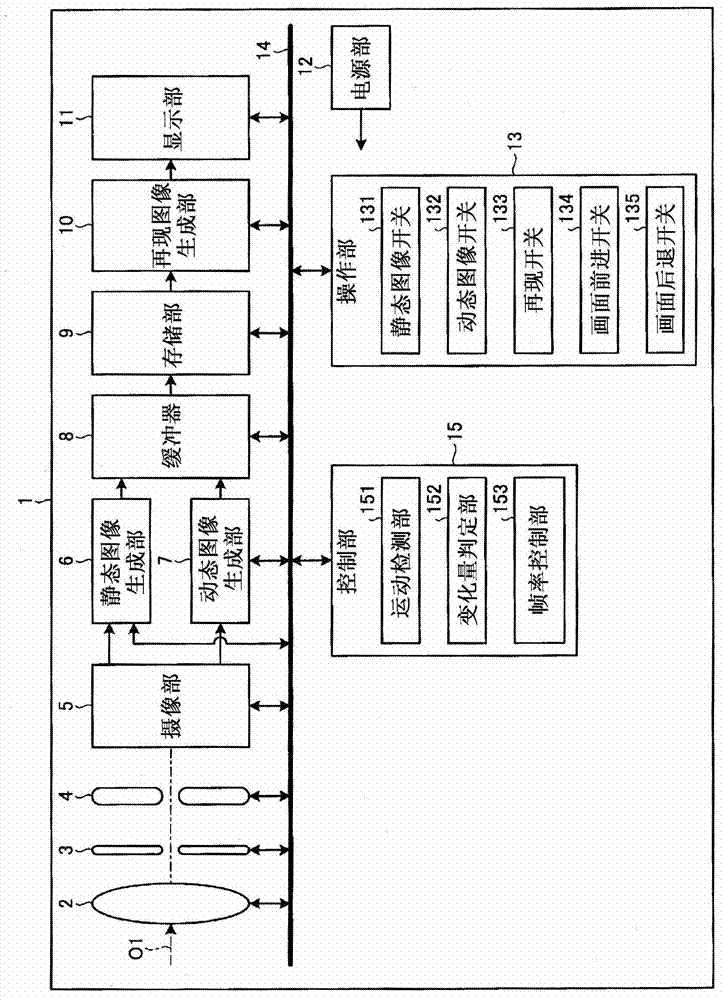
[0035] figure 1 It is a block diagram showing the configuration of the video equipment according to Embodiment 1 of the present invention. figure 1 The illustrated imaging device 1 has a lens unit 2, an aperture unit 3, a shutter unit 4, an imaging unit 5, a still image generating unit 6, a moving image generating unit 7, a buffer 8, a storage unit 9, a reproduced image generating unit 10, a display part 11, power supply part 12, operation part 13, bus 14 and control part 15.
[0036] The lens unit 2 is composed of one or more lenses, motors, etc., and collects light from a predetermined field of view to form an image on the imaging unit 5 . The lens unit 2 has an optical zoom function for changing the angle of view and a focus function for adjusting the focus. The lens unit 2 moves the lens along the optical axis O1 based on an instruction signal input from the control unit 15 via the bus 14 to change the focus position and angle of view of the lens unit 2 .
[0037] The a...
Embodiment approach 2
[0087] Next, Embodiment 2 of the present invention will be described. In Embodiment 2 of the present invention, only the imaging processing of the operation performed by the video device of Embodiment 1 is different, and the configuration of the video device is the same as that of the video device of the above-mentioned embodiment. Therefore, only the imaging processing of the imaging device according to Embodiment 2 of the present invention will be described below. In addition, in description of drawings, the same code|symbol is attached|subjected to the same part.
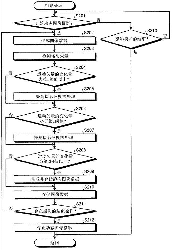
[0088] Figure 7 It shows the photographing process performed by the imaging device 1 of the second embodiment ( figure 2 A flow chart of the outline of step S103). Figure 8 It is a diagram showing a sequence chart of imaging processing of the imaging device 1 . Figure 8 (a) shows the timing of video shooting when the imaging unit 5 generates video data. Figure 8 (b) shows the shooting timing of still im...
Embodiment approach 3
[0096] Next, Embodiment 3 of the present invention will be described. In Embodiment 3 of the present invention, only the photographing process performed by the imaging device of the above-mentioned embodiment is different, and the configuration of the imaging device is the same as that of the imaging device of the above-mentioned embodiment. Therefore, only the imaging processing of the imaging device according to Embodiment 3 of the present invention will be described below.
[0097] Figure 9 It shows the photographing process performed by the imaging device 1 according to Embodiment 3 ( figure 2 A flow chart of the outline of step S103).
[0098] Such as Figure 9 As shown, steps S501 to S507 are respectively related to image 3 Corresponding to steps S201 to S207 of . Step S508~step S509 respectively and image 3 Corresponding to step S210 to step S211 of . Step S514 and image 3 corresponding to step S213.
[0099] In step S510 , the motion detection unit 151 de...
PUM
 Abstract
Description
Claims
Application Information